Lincoln Navigator: Rear Drive Axle/Differential - Vehicles With: Ford 9.75 Inch Ring Gear / Rear Drive Axle and Differential - Vehicles With: Electronic Limited-Slip Differential. Diagnosis and Testing
Diagnostic Trouble Code (DTC) Chart
Diagnostics in this manual assume a certain skill level and knowledge of Ford-specific diagnostic practices.
REFER to: Diagnostic Methods (100-00 General Information, Description and Operation).
| Module | DTC | Description | Action |
|---|---|---|---|
| DCMR | P0745:12 | Pressure Control Solenoid A: Circuit Short To Battery | GO to Pinpoint Test E |
| DCMR | P0745:13 | Pressure Control Solenoid A: Circuit Open | GO to Pinpoint Test E |
| DCMR | P0745:19 | Pressure Control Solenoid A: Circuit Current Above Threshold | GO to Pinpoint Test E |
| DCMR | P0932:12 | Hydraulic Pressure Sensor Circuit: Circuit Short To Battery | GO to Pinpoint Test A |
| DCMR | P0932:14 | Hydraulic Pressure Sensor Circuit: Circuit Short To Ground Or Open | GO to Pinpoint Test A |
| DCMR | P0932:16 | Hydraulic Pressure Sensor Circuit: Circuit Voltage Below Threshold | GO to Pinpoint Test A |
| DCMR | P0932:17 | Hydraulic Pressure Sensor Circuit: Circuit Voltage Above Threshold | GO to Pinpoint Test A |
| DCMR | P0937:12 | Hydraulic Oil Temperature Sensor Circuit: Circuit Short To Battery | GO to Pinpoint Test C |
| DCMR | P0937:14 | Hydraulic Oil Temperature Sensor Circuit: Circuit Short To Ground Or Open | GO to Pinpoint Test C |
| DCMR | P0A90:11 | Drive Motor 'A' Performance: Circuit Short To Ground | GO to Pinpoint Test D |
| DCMR | P0A90:13 | Drive Motor 'A' Performance: Circuit Open | GO to Pinpoint Test D |
| DCMR | P0A90:19 | Drive Motor 'A' Performance: Circuit Current Above Threshold | GO to Pinpoint Test D |
| DCMR | P170E:92 | Clutch Delivered Torque Performance: Performance Or Incorrect Operation | GO to Pinpoint Test Q |
| DCMR | P173A:12 | Clutch Actuator Position Sensor Circuit Range/Performance: Circuit Short To Battery | GO to Pinpoint Test B |
| DCMR | P173A:14 | Clutch Actuator Position Sensor Circuit Range/Performance: Circuit Short To Ground Or Open | GO to Pinpoint Test B |
| DCMR | P173A:16 | Clutch Actuator Position Sensor Circuit Range/Performance: Circuit Voltage Below Threshold | GO to Pinpoint Test B |
| DCMR | P173A:17 | Clutch Actuator Position Sensor Circuit Range/Performance: Circuit Voltage Above Threshold | GO to Pinpoint Test B |
| DCMR | U0100:00 | Lost Communication With ECM/PCM 'A': No Sub Type Information | GO to Pinpoint Test F |
| DCMR | U0102:00 | Lost Communication with Transfer Case Control Module: No Sub Type Information | GO to Pinpoint Test G |
| DCMR | U0121:00 | Lost Communication With Anti-Lock Brake System (ABS) Control Module 'A': No Sub Type Information | GO to Pinpoint Test H |
| DCMR | U0140:00 | Lost Communication With Body Control Module: No Sub Type Information | GO to Pinpoint Test I |
| DCMR | U0146:00 | Lost Communication With Serial Data Gateway 'A': No Sub Type Information | GO to Pinpoint Test J |
| DCMR | U0401:00 | Invalid Data Received from ECM/PCM A: No Sub Type Information | GO to Pinpoint Test R |
| DCMR | U0415:00 | Invalid Data Received from Anti-Lock Brake System (ABS) Control Module 'A': No Sub Type Information | GO to Pinpoint Test R |
| DCMR | U0422:00 | Invalid Data Received From Body Control Module: No Sub Type Information | GO to Pinpoint Test R |
| DCMR | U1000:00 | Solid State Driver Protection Active -Driver Disabled: No Sub Type Information | GO to Pinpoint Test K |
| DCMR | U1000:01 | Solid State Driver Protection Active -Driver Disabled: General Electrical Failure | GO to Pinpoint Test L |
| DCMR | U200A:16 | Control Module Internal Power A: Circuit Voltage Below Threshold | GO to Pinpoint Test M |
| DCMR | U200A:17 | Control Module Internal Power A: Circuit Voltage Above Threshold | GO to Pinpoint Test M |
| DCMR | U3000:49 | Control Module: Internal Electronic Failure | GO to Pinpoint Test N |
| DCMR | U3006:16 | Control Module Input Power 'A' Circuit/Open: Circuit Voltage Below Threshold | GO to Pinpoint Test O |
| DCMR | U3006:17 | Control Module Input Power 'A' Circuit/Open: Circuit Voltage Above Threshold | GO to Pinpoint Test O |
Global Customer Symptom Code (GCSC) Chart
Diagnostics in this manual assume a certain skill level and knowledge of Ford-specific diagnostic practices.
REFER to: Diagnostic Methods (100-00 General Information, Description and Operation).
| Symptom | Action |
|---|---|
| Driver Aid & Information > Warning Indicators/Messages/Chimes > AdvanceTrac/Traction Control > Inoperative | GO to Pinpoint Test P |
| Driver Aid & Information > Warning Indicators/Messages/Chimes > Charging System > Flashes | GO to Pinpoint Test A |
| Driver Aid & Information > Warning Indicators/Messages/Chimes > Charging System > Inoperative | GO to Pinpoint Test A |
| Driver Aid & Information > Warning Indicators/Messages/Chimes > Charging System > Stays On | GO to Pinpoint Test A |
| Driver Aid & Information > Warning Indicators/Messages/Chimes > Overdrive Off > Inoperative | GO to Pinpoint Test P |
| Driver Aid & Information > Driver Alert > Performance > Inoperative | GO to Pinpoint Test P |
| Start/Run/Move > Moving > Engagement Quality > Both (FWD and REV) | GO to Pinpoint Test P |
Symptom Chart
Symptom Chart Electronic Limited Slip Differential (ELSD) System
Diagnostics in this manual assume a certain skill level and knowledge of Ford-specific diagnostic practices.
REFER to: Diagnostic Methods (100-00 General Information, Description and Operation).
| Condition | Possible Sources | Actions |
|---|---|---|
| The DCMR does not respond to the scan tool |
|
|
| Vehicle has no or inadequate torque at rear wheels |
|
|
| Vehicle binds in a turn or resists turning/pulsates |
|
|
| The ELD IPC indicator is never on - the ELD switch LED does not light |
|
|
Pinpoint Tests
|
Refer to Wiring Diagrams Cell 34 for schematic and connector information. Normal Operation and Fault Conditions The DCMR provides 5v to the differential pressure sensor and differential oil temperature sensor on the PRESSURE SENSOR SUPPLY circuit C3396-7 and ground for the differential pressure sensor on the ACCUMULATOR PRESSURE GND circuit C3396-12. The differential pressure sensor provides a variable voltage signal relative to the fluid pressure in the accumulator to the DCMR on the ACCUMULATOR PRESSURE INPUT circuit C3396-9. The DCMR monitors the sensor circuits for short to voltage, short to ground/open, and pressure higher or er than expected. 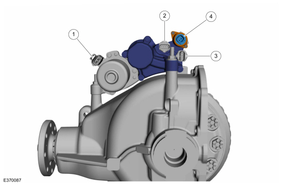
DTC Fault Trigger Conditions
Possible Sources
|
||||||||||||||||||||||||||||||
| A1 CHECK DCMR (DIFFERENTIAL CONTROL MODULE REAR) FOR PRESSURE SENSOR SUPPLY FAULT | ||||||||||||||||||||||||||||||
Is DTC U200A:16 or U200A:17 present?
|
||||||||||||||||||||||||||||||
| A2 CHECK HCU (HYDRAULIC CONTROL UNIT) FLUID LEVEL | ||||||||||||||||||||||||||||||
Is the HCU fluid level within specification?
|
||||||||||||||||||||||||||||||
| A3 CHECK THE DIFFERENTIAL PRESSURE CIRCUITS FOR OPEN CIRCUIT | ||||||||||||||||||||||||||||||
Are the resistances less than 3 ohms?
|
||||||||||||||||||||||||||||||
| A4 CHECK THE DIFFERENTIAL PRESSURE CIRCUITS FOR SHORT TO GROUND | ||||||||||||||||||||||||||||||
Are the resistances greater than 10,000 ohms
|
||||||||||||||||||||||||||||||
| A5 CHECK THE DIFFERENTIAL PRESSURE SENSOR CIRCUITS FOR SHORT TO VOLTAGE | ||||||||||||||||||||||||||||||
Is any voltage present?
|
||||||||||||||||||||||||||||||
| A6 CHECK THE DIFFERENTIAL PRESSURE SENSOR RESISTANCE | ||||||||||||||||||||||||||||||
Is the resistance between 1500 to 2500 ohms?
|
||||||||||||||||||||||||||||||
| A7 CHECK THE DIFFERENTIAL PRESSURE SENSOR FOR A SHORT TO GROUND | ||||||||||||||||||||||||||||||
Is the resistance greater than 10,000 ohms?
|
||||||||||||||||||||||||||||||
| A8 CHECK THE DIFFERENTIAL PRESSURE SENSOR GROUND | ||||||||||||||||||||||||||||||
Is the resistance greater than 5 ohms?
|
||||||||||||||||||||||||||||||
| A9 CHECK FOR CORRECT DCMR (DIFFERENTIAL CONTROL MODULE REAR) OPERATION | ||||||||||||||||||||||||||||||
Is the concern still present?
|


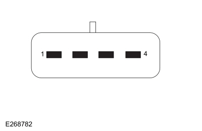 Differential pressure sensor component side, pin 4.
|
Refer to Wiring Diagrams Cell 34 for schematic and connector information. Normal Operation and Fault Conditions The eLSD system uses input data from a Clutch actuator position sensor as part of the normal system operation. Loss of this sensor input data causes the system to enter a fault condition. DTC Fault Trigger Conditions
Possible Sources
|
|||||||||||||||
| B1 CHECK HCU (HYDRAULIC CONTROL UNIT) FLUID LEVEL | |||||||||||||||
Is the HCU fluid level within specification?
|
|||||||||||||||
| B2 CHECK FOR DCMR (DIFFERENTIAL CONTROL MODULE REAR) DTCS (DIAGNOSTIC TROUBLE CODE) | |||||||||||||||
Are any DTC s present?
|
|||||||||||||||
| B3 CHECK THE OIL TEMPERATURE / PRESSURE SENSOR CIRCUIT FOR SHORT TO VOLTAGE | |||||||||||||||
Is the voltage greater than 5.5 volts?
|
|||||||||||||||
| B4 CHECK THE OIL TEMPERATURE / PRESSURE SENSOR CIRCUIT RESISTANCE | |||||||||||||||
Is the resistance between 1500 to 2500 ohms?
|
|||||||||||||||
| B5 CHECK THE OIL TEMPERATURE / PRESSURE SENSOR CIRCUIT FOR A SHORT TO GROUND | |||||||||||||||
Is the resistance greater than 10,000 ohms?
|
|||||||||||||||
| B6 CHECK THE OIL TEMPERATURE / PRESSURE SENSOR GROUND | |||||||||||||||
Is the resistance greater than 5 ohms?
|
|||||||||||||||
| B7 CHECK THE OIL TEMPERATURE / PRESSURE CIRCUIT FOR A SHORT TO GROUND | |||||||||||||||
Is the resistance greater than 10,000 ohms?
|
|||||||||||||||
| B8 CHECK THE OIL TEMPERATURE / PRESSURE SENSOR SIGNAL CIRCUIT FOR A SHORT TO CHASSIS GROUND | |||||||||||||||
Is the resistance greater than 10,000 ohms?
|
|||||||||||||||
| B9 CHECK THE OIL TEMPERATURE / PRESSURE SENSOR VOTAGE CIRCUIT FOR A SHORT TO GROUND | |||||||||||||||
Is the resistance greater than 10,000 ohms?
|
|||||||||||||||
| B10 CHECK THE OIL TEMPERATURE / PRESSURE SENSOR VOTAGE CIRCUIT FOR BELOW THRESHOLD | |||||||||||||||
Is the voltage greater than 4.5 volts?
|
|||||||||||||||
| B11 CHECK DCMR (DIFFERENTIAL CONTROL MODULE REAR) FOR VCC SUPPLY FAULT | |||||||||||||||
Is DTC U200A:16 present?
|
|||||||||||||||
| B12 CHECK THE OIL TEMPERATURE / PRESSURE SENSOR VOTAGE CIRCUIT FOR ABOVE THRESHOLD | |||||||||||||||
Is voltage greater than 5.5 volts?
|
|||||||||||||||
| B13 CHECK THE OIL TEMPERATURE / PRESSURE VOLTAGE CIRCUIT FOR A SHORT TO VOLTAGE | |||||||||||||||
Is any voltage detected?
|
|||||||||||||||
| B14 CHECK FOR CORRECT DCMR OPERATION | |||||||||||||||
Is the concern still present?
|
|
Refer to Wiring Diagrams Cell 34 for schematic and connector information. Normal Operation and Fault Conditions The eLSD system uses input data from a oil temperature/pressure sensor as part of the normal system operation. Loss of this sensor input data causes the system to enter a fault condition. DTC Fault Trigger Conditions
Possible Sources
|
||||||||||
| C1 CHECK FOR DCMR (DIFFERENTIAL CONTROL MODULE REAR) DTCS (DIAGNOSTIC TROUBLE CODE) | ||||||||||
Are any DTC present?
|
||||||||||
| C2 CHECK THE OIL TEMPERATURE/PRESSURE SENSOR RESISTANCE | ||||||||||
Is the resistance between 1500 to 2500 ohms?
|
||||||||||
| C3 CHECK THE OIL TEMPERATURE/PRESSURE SENSOR CIRCUIT FOR SHORT TO VOLTAGE | ||||||||||
Is any voltage detected?
|
||||||||||
| C4 CHECK THE OIL TEMPERATURE/PRESSURE SENSOR | ||||||||||
Is the resistance greater than 5 ohms?
|
||||||||||
| C5 CHECK THE OIL TEMPERATURE/PRESSURE CIRCUIT FOR AN OPEN | ||||||||||
Is the resistance less than 3 ohms?
|
||||||||||
| C6 CHECK THE OIL TEMPERATURE/PRESSURE CIRCUIT FOR A SHORT TO GROUND | ||||||||||
Is the resistance greater than 10,000 ohms?
|
||||||||||
| C7 CHECK FOR CORRECT DCMR (DIFFERENTIAL CONTROL MODULE REAR) OPERATION | ||||||||||
Is the concern still present?
|
|
Refer to Wiring Diagrams Cell 34 for schematic and connector information. Normal Operation and Fault Conditions The DCMR provides 5v to the differential pressure sensor and differential oil temperature sensor on the PRESSURE SENSOR SUPPLY circuit C3396-7 and ground for the differential pressure sensor on the ACCUMULATOR PRESSURE GND circuit C3396-12. The differential pressure sensor provides a variable voltage signal relative to the fluid pressure in the accumulator to the DCMR on the ACCUMULATOR PRESSURE INPUT circuit C3396-9. The DCMR monitors the sensor circuits for short to voltage, short to ground/open, and pressure higher or lower than expected.
DTC Fault Trigger Conditions
Possible Sources
|
|||||||||||||||||||||||||||
| D1 CHECK FOR DCMR DTC | |||||||||||||||||||||||||||
Is DTC P0A90:11 or P0A90:13 or P0A90:19 recorded?
|
|||||||||||||||||||||||||||
| D2 CHECK THE OIL PUMP MOTOR CIRCUIT FOR AN INTERNAL SHORT TO GROUND | |||||||||||||||||||||||||||
Is the resistance greater than 10,000 ohms?
|
|||||||||||||||||||||||||||
| D3 CHECK THE HYDRAULIC PUMP MOTOR CIRCUIT FOR SHORT TO GROUND | |||||||||||||||||||||||||||
Are the resistances greater than 10,000 ohms?
|
|||||||||||||||||||||||||||
| D4 CHECK THE DIFFERENTIAL PUMP MOTOR FOR AN OPEN | |||||||||||||||||||||||||||
Is the resistance greater than 10 ohms?
|
|||||||||||||||||||||||||||
| D5 CHECK THE HYDRAULIC PUMP MOTOR CIRCUIT FOR AN OPEN | |||||||||||||||||||||||||||
Is the resistance less than 3 ohms?
|
|||||||||||||||||||||||||||
| D6 CHECK THE HYDRAULIC PUMP MOTOR CIRCUITS FOR A SHORT TOGETHER | |||||||||||||||||||||||||||
Is the resistances greater than 10,000 ohms?
|
|||||||||||||||||||||||||||
| D7 CHECK THE HYDRAULIC PUMP MOTOR CIRCUIT FOR SHORT TO GROUND | |||||||||||||||||||||||||||
Are the resistances greater than 10,000 ohms?
|
|||||||||||||||||||||||||||
| D8 CHECK FOR CORRECT DCMR (DIFFERENTIAL CONTROL MODULE REAR) OPERATION | |||||||||||||||||||||||||||
Is the concern still present?
|
|
Refer to Wiring Diagrams Cell 34 for schematic and connector information. Normal Operation and Fault Conditions The eLSD system HCU pressure is control by pressure control valve which receives signal from DCMR as part of the normal system operation. Loss of this signal data causes the system to set a DTC . Hydraulic Control Unit Electrical Connectors
DTC Fault Trigger Conditions
Possible Sources
|
|||||||||||||
| E1 CHECK FOR DCMR (DIFFERENTIAL CONTROL MODULE REAR) DTCS (DIAGNOSTIC TROUBLE CODE) | |||||||||||||
Are any DTC present?
|
|||||||||||||
| E2 CHECK THE PRESSURE CONTROL VALVE FOR SHORT TO BATTERY | |||||||||||||
Is any voltage detected?
|
|||||||||||||
| E3 CHECK THE PRESSURE CONTROL VALVE FOR AN OPEN | |||||||||||||
Is the resistance greater than 10 ohms?
|
|||||||||||||
| E4 CHECK THE PRESSURE CONTROL VALVE CIRCUIT FOR AN OPEN | |||||||||||||
Are the resistances less than 3 ohms?
|
|||||||||||||
| E5 CHECK THE PRESSURE CONTROL VALVE CIRCUIT FOR A SHORT TO GROUND | |||||||||||||
Is the resistance greater than 10,000 ohms?
|
|||||||||||||
| E6 CHECK THE PRESSURE CONTROL VALVE CIRCUIT FOR A SHORT TO CHASSIS GROUND | |||||||||||||
Is resistance greater than 10,000 ohms?
|
|||||||||||||
| E7 CHECK THE PRESSURE CONTROL VALVE FOR OPEN | |||||||||||||
Is the resistance greater than 10 ohms?
|
|||||||||||||
| E8 CHECK FOR CORRECT DCMR (DIFFERENTIAL CONTROL MODULE REAR) OPERATION | |||||||||||||
Is the concern still present?
|
|
Refer to Wiring Diagrams Cell 34 for schematic and connector information. Normal Operation and Fault Conditions The DCMR sets DTC U0100 when it has not received messages from the PCM for more than 5 seconds with ignition in RUN and battery voltage in range. Other modules that require data from the PCM all set communication DTC s and may also exhibit system function concerns. DTC Fault Trigger Conditions
Possible Sources
|
||||||
| F1 VERIFY THE SCAN TOOL COMMUNICATES WITH THE PCM (POWERTRAIN CONTROL MODULE) | ||||||
Can a vehicle session be established?
|
||||||
| F2 CHECK THE DCMR (DIFFERENTIAL CONTROL MODULE REAR) CONTINUOUS MEMORY DTC (DIAGNOSTIC TROUBLE CODE)S | ||||||
Is DTC U0100:00 still present?
|
||||||
| F3 RETRIEVE THE RECORDED DTC (DIAGNOSTIC TROUBLE CODE)S FROM THE PCM (POWERTRAIN CONTROL MODULE) KOEO (KEY ON, ENGINE OFF) SELF-TEST | ||||||
Are any DTC recorded?
|
||||||
| F4 RETRIEVE THE RECORDED DTC (DIAGNOSTIC TROUBLE CODE)S FROM THE DCMR (DIFFERENTIAL CONTROL MODULE REAR) SELF-TEST | ||||||
Is DTC P0562:00 or P0563:00 recorded?
|
||||||
| F5 CHECK FOR DTC (DIAGNOSTIC TROUBLE CODE)S U0100 SET IN OTHER MODULES | ||||||
Is the DTC U0100:00 set in other modules on the network?
|
||||||
| F6 CHECK FOR CORRECT PCM (POWERTRAIN CONTROL MODULE) OPERATION | ||||||
Is the concern still present?
|
||||||
| F7 CHECK FOR CORRECT DCMR (DIFFERENTIAL CONTROL MODULE REAR) OPERATION | ||||||
Is the concern still present?
|
 Click here to access Guided Routine (PCM).
|
Refer to Wiring Diagrams Cell 34 for schematic and connector information. Normal Operation and Fault Conditions
REFER to: Rear
Drive Axle and Differential - Vehicles With: Electronic Limited-Slip
Differential - System Operation and Component Description (205-02 Rear
Drive Axle/Differential - Vehicles With: Ford 9.75 Inch Ring Gear,
Description and Operation). DTC Fault Trigger Conditions
Possible Sources
|
||||||
| G1 VERIFY THE CUSTOMER CONCERN | ||||||
Is an observable symptom present?
|
||||||
| G2 CHECK THE COMMUNICATION NETWORK | ||||||
Does the DCMR pass the network test?
|
||||||
| G3 PERFORM THE DCMR MODULE SELF-TEST | ||||||
Are any non-network DTC s recorded?
|
||||||
| G4 CHECK THE GWM DTC (DIAGNOSTIC TROUBLE CODE)S | ||||||
Are any DTC s recorded?
|
||||||
| G5 CHECK FOR OTHER CAUSES OF COMMUNICATION NETWORK CONCERN | ||||||
|
NOTE: If new modules were installed prior to the DTC being set, the module configuration can be incorrectly set during the PMI or the PMI may not have been carried out.
Is the observable symptom still present?
|
||||||
| G6 CHECK FOR CORRECT DCMR OPERATION | ||||||
Is the concern still present?
|
|
Refer to Wiring Diagrams Cell 34 for schematic and connector information. Normal Operation and Fault Conditions The DCMR sets the DTC U0121 when key messages such as wheel speed, brake pressure or torque are not received for longer than 5 seconds. This loss of key messages degrades the transmission functionality. Other modules that require data from the ABS module all set communication DTC s and may also exhibit system function concerns. DTC Fault Trigger Conditions
Possible Sources
|
||||||
| H1 VERIFY THE SCAN TOOL COMMUNICATES WITH THE ABS (ANTI-LOCK BRAKE SYSTEM) | ||||||
Can a vehicle session be established?
|
||||||
| H2 CHECK THE BCM (BODY CONTROL MODULE) CMDTC (CONTINUOUS MEMORY DIAGNOSTIC TROUBLE CODE)S | ||||||
Is DTC U0121 retrieved again?
|
||||||
| H3 RETRIEVE THE RECORDED DTC (DIAGNOSTIC TROUBLE CODE)S FROM THE ABS (ANTI-LOCK BRAKE SYSTEM) MODULE SELF-TEST | ||||||
Are any DTC s recorded?
|
||||||
| H4 RETRIEVE THE RECORDED DTC (DIAGNOSTIC TROUBLE CODE)S FROM THE PCM SELF-TEST | ||||||
Is DTC P0562:00 or P0563:00 recorded?
|
||||||
| H5 CHECK FOR DTC (DIAGNOSTIC TROUBLE CODE) U0121 SET IN OTHER MODULES | ||||||
Is DTC U0121 set in other modules on the network?
|
||||||
| H6 CHECK FOR CORRECT ABS (ANTI-LOCK BRAKE SYSTEM) MODULE OPERATION | ||||||
Is the concern still present?
|
||||||
| H7 CHECK FOR CORRECT BCM (BODY CONTROL MODULE) OPERATION | ||||||
Is the concern still present?
|
|
Refer to Wiring Diagrams Cell 34 for schematic and connector information. Normal Operation and Fault Conditions
REFER to: Rear
Drive Axle and Differential - Vehicles With: Electronic Limited-Slip
Differential - System Operation and Component Description (205-02 Rear
Drive Axle/Differential - Vehicles With: Ford 9.75 Inch Ring Gear,
Description and Operation). DTC Fault Trigger Conditions
Possible Sources |
||||||
| I1 VERIFY THE CUSTOMER CONCERN | ||||||
Is an observable symptom present?
|
||||||
| I2 CHECK THE COMMUNICATION NETWORK | ||||||
Does the BCM pass the network test?
|
||||||
| I3 PERFORM THE DCMR SELF-TEST | ||||||
Are any non-network DTC present?
|
||||||
| I4 CHECK THE GWM DTC (DIAGNOSTIC TROUBLE CODE)S | ||||||
Are any DTC recorded?
|
||||||
| I5 PERFORM THE BCM SELF-TEST | ||||||
Are any non-network DTC present?
|
||||||
| I6 CHECK FOR OTHER CAUSES OF COMMUNICATION NETWORK CONCERN | ||||||
|
NOTE: If new modules were installed prior to the DTC being set, the module configuration may be incorrectly set during the PMI, or the PMI may not have been carried out.
Is the observable symptom still present?
|
||||||
| I7 CHECK FOR CORRECT BCM OPERATION | ||||||
Is the concern still present?
|
|
Normal Operation and Fault Conditions The DCMR communicates with the GWM over the CAN . If the DCMR does not receive messages from the GWM , features such as the keyless entry can be inoperative. DTC Fault Trigger Conditions
Possible Sources
|
||||||
| J1 VERIFY THE CUSTOMER CONCERN | ||||||
Is an observable symptom present?
|
||||||
| J2 CHECK THE COMMUNICATION NETWORK | ||||||
Does the GWM pass the network test?
|
||||||
| J3 CHECK THE GWM (GATEWAY MODULE A) DTC (DIAGNOSTIC TROUBLE CODE)S | ||||||
Are any DTC s recorded?
|
||||||
| J4 CHECK FOR CHARGING SYSTEM RELATED DTC (DIAGNOSTIC TROUBLE CODE)S | ||||||
Are any battery voltage related DTC retrieved?
|
||||||
| J5 RECHECK THE DCMR DTC (DIAGNOSTIC TROUBLE CODE)S | ||||||
|
NOTE: If new modules were installed prior to the DTC being set, the module configuration may be incorrectly set during PMI or the PMI may not have been performed.
Is DTC U0146:00 still present?
|
||||||
| J6 CHECK FOR DTC U0146 SET IN OTHER MODULES | ||||||
Is DTC U0146 set in other modules?
|
||||||
| J7 CHECK FOR CORRECT GWM (GATEWAY MODULE A) OPERATION | ||||||
Is the concern still present?
|
|
Normal Operation and Fault Conditions The DCMR
uses a solid state driver (Field Effect Transistor (FET)) to control
the output of several vehicle systems. When an overload occurs on any of
these drivers, the DCMR
disables the output and tracks the number of repetitive faults on each
of these circuits. The module compares this number of overloads to
50,000 progressive thresholds established for each circuit. At each
threshold, DTC U1000:00 sets along with the DTC associated with the
affected circuit. REFER to: Module Controlled Functions - System
Operation and Component Description (419-10 Multifunction Electronic
Modules, Description and Operation). DTC Fault Trigger Conditions
Possible Sources
|
||||||
| K1 REVIEW THE DTC () | ||||||
Is DTC P0745:12 present besides U1000:00?
|
||||||
| K2 REPEAT THE DCMR SELF-TEST | ||||||
Is DTC U1000:00 still present?
|
|
Normal Operation and Fault Conditions The DCMR
uses a solid state driver (Field Effect Transistor (FET)) to control
the output of several vehicle systems. When an overload occurs on any of
these drivers, the DCMR
disables the output and tracks the number of repetitive faults on each
of these circuits. The module compares this number of overloads to
50,000 progressive thresholds established for each circuit. At each
threshold, DTC U1000:00 sets along with the DTC associated with the
affected circuit. REFER to: Module Controlled Functions - System
Operation and Component Description (419-10 Multifunction Electronic
Modules, Description and Operation). DTC Fault Trigger Conditions
Possible Sources
|
||||||
| L1 REVIEW THE DTC (DIAGNOSTIC TROUBLE CODE)S | ||||||
Is DTC P0745:12 present besides U1000:01?
|
||||||
| L2 REPEAT THE DCMR (DIFFERENTIAL CONTROL MODULE REAR) SELF-TEST | ||||||
Is DTC U1000:01 still present?
|
|
Refer to Wiring Diagrams Cell 34 for schematic and connector information. Normal Operation and Fault Conditions The DCMR monitor the internal circriuty ans memory for error. If a fault is detected multiple times, a DTC is set. DTC Fault Trigger Conditions
Possible Sources
|
|||||||||
| M1 REVIEW THE DTC (DIAGNOSTIC TROUBLE CODE)S | |||||||||
Are DTC s U3006:16 or U3006:17 present?
|
|||||||||
| M2 CHECK FOR CORRECT DCMR OPERATION | |||||||||
Is the concern still present?
|
|
Normal Operation and Fault Conditions The DCMR uses a solid state driver FET to control the output of
several vehicle systems. When an overload occurs on any of these
drivers, the DCMR
disables the output and tracks the number of repetitive faults on each
of these circuits. The module compares this number of overloads to
1,00,000 progressive thresholds established for each circuit. When the
maximum number of threshold for each circuit are reached, DTC U3000:49
sets along with the DTC associated with the affected circuit. REFER to:
Module Controlled Functions - System Operation and Component Description
(419-10 Multifunction Electronic Modules, Description and Operation). DTC Fault Trigger Conditions
Possible Sources
|
||||||
| N1 REVIEW THE DTC DIAGNOSTIC TROUBLE CODE)S | ||||||
Is DTC P0745:12 or P0A90:19 present besides U3002:49?
|
||||||
| N2 REPEAT THE DCMR (DIFFERENTIAL CONTROL MODULE REAR) SELF-TEST | ||||||
Is DTC U3000:49 still present?
|
|
Normal Operation and Fault Conditions The DCMR uses various sensors with a reference power supply from the DCMR . If the power to the sensor is out of range it may give an erroneous reading. In this case DTC U3006:16, or U3006:17 may be set DTC Fault Trigger Conditions
Possible Sources
|
||||||||||
| O1 REVIEW THE DTC (DIAGNOSTIC TROUBLE CODE)S | ||||||||||
Are DTC s P0562:00 or P0563:00 set in other module?
|
||||||||||
| O2 CHECK VOLTAGE TO THE DCMR (DIFFERENTIAL CONTROL MODULE REAR) | ||||||||||
Is the voltage within 1 volt of battery voltage?
|
|
Normal Operation and Fault Conditions The ELD is a function of the eLSD . The ELD switch is part of the 4x4 switch module, also known by the scan tool as the ATCM . When the ELD is switched on, the ATCM sends a request over the HS-CAN2 requesting the DCMR apply full torque to lock both rear axles. It also sends a message to the IPC to illuminate the ELD indicator. Possible Sources
|
||||||||||||||||
| P1 CHECK FOR DTC (DIAGNOSTIC TROUBLE CODE)S | ||||||||||||||||
Are any DCMR DTC s retrieved?
|
||||||||||||||||
| P2 CHECK FOR NETWORK DTC (DIAGNOSTIC TROUBLE CODE)S | ||||||||||||||||
Are any network DTC retrieved for the GWM , ATCM , IPC or DCMR ?
|
||||||||||||||||
| P3 CHECK ELD (ELECTRONIC LOCKING DIFFERENTIAL) SWITCH LED AND IPC (INSTRUMENT PANEL CLUSTER) ELD (ELECTRONIC LOCKING DIFFERENTIAL) INDICATOR OPERATION | ||||||||||||||||
Do both the IPC indicator and the ELD switch LED illuminate when the switch is pressed?
|
||||||||||||||||
| P4 CHECK THE POWER TO THE MSS SWITCH MODULE | ||||||||||||||||
Are the voltage values within specification?
|
||||||||||||||||
| P5 CHECK THE GROUND CIRCUIT TO THE 4X4 SWITCH MODULE | ||||||||||||||||
Is the resistance less than 3 ohms?
|
|
Refer to Wiring Diagrams Cell 34 for schematic and connector information. Normal Operation and Fault Conditions The DCMR provides a variable 0-12v to the differential pump motor on the PUMP SUPPLY circuit C3396-4 and ground for the differential pump motor on the MOTOR GND circuit C3396-3 to maintain a certain amount of pressure in the accumulator. The differential pressure sensor provides a variable voltage signal relative to the fluid pressure in the accumulator to the DCMR on the ACCUMULATOR PRESSURE INPUT circuit C3396-9. When the DCMR determines the eLSD needs to be applied, the DCMR provides a variable 0-12v to the differential control valve (Pressure Control Solenoid A). The differential oil temperature sensor provides a variable voltage signal relative to the fluid pressure in the eLSD apply hydraulic circuit to the DCMR on the CLUTCH PRESSURE INPUT circuit C3396-8. If wheel slip is not controlled or eliminated within a certain amount of time and pressure, DTC P170E:92 will be stored in continuous memory.
DTC Fault Trigger Conditions
Possible Sources
|
|||||||||||||||||||||
| Q1 CHECK FOR OTHER DCMR FAULTS | |||||||||||||||||||||
Is DTC P170E:92 the only code present in the DCMR ?
|
|||||||||||||||||||||
| Q2 CHECK HCU (HYDRAULIC CONTROL UNIT) FLUID LEVEL | |||||||||||||||||||||
Is the fluid level within specification?
|
|||||||||||||||||||||
| Q3 INSPECT HYDRAULIC ACTUATOR FOR CONTAMINATION OR DAMAGE | |||||||||||||||||||||
Does the piston move freely with no indication of damage or contamination?
|
|
Refer to Wiring Diagrams Cell 34 for schematic and connector information. DTC Fault Trigger Conditions
Possible Sources
|
||||||||||||
| R1 VERIFY THE SCAN TOOL COMMUNICATES WITH THE PCM | ||||||||||||
Can a vehicle session be established?
|
||||||||||||
| R2 VERIFY THE SCAN TOOL COMMUNICATES WITH THE ABS (ANTI-LOCK BRAKE SYSTEM) MODULE | ||||||||||||
Can a vehicle session be established?
|
||||||||||||
| R3 RETRIEVE AND DIAGNOSIS ALL DTC (DIAGNOSTIC TROUBLE CODE) FROM ABS MODULE | ||||||||||||
Is any DTC present?
|
||||||||||||
| R4 RETRIEVE AND DIAGNOSIS ALL DTC (DIAGNOSTIC TROUBLE CODE) FROM GWM MODULE | ||||||||||||
Is any DTC present?
|
||||||||||||
| R5 CHECK THE SUSPECT MODULE FOR DTC | ||||||||||||
Are any DTC set in the suspect module?
|
||||||||||||
| R6 ATTEMPT TO DUPLICATE DTC (DIAGNOSTIC TROUBLE CODE) | ||||||||||||
Did the valid data DTC set again?
|
||||||||||||
| R7 INSPECT THE HS-CAN2 CONNECTORS | ||||||||||||
Is the concern still present?
|
 Rear Drive Axle and Differential. Diagnosis and Testing
Symptom Chart(s)
Diagnostics in this manual assume a certain skill level and knowledge of Ford-specific diagnostic practices. REFER to: Diagnostic Methods (100-00 General Information, Description and Operation)...
 Differential Draining and Filling. General Procedures
Draining
With the vehicle in NEUTRAL, position it on a hoist.
Refer to: Jacking and Lifting (100-02 Jacking and Lifting, Description and Operation)...
Other information:
Lincoln Navigator 2018-2024 Workshop Manual: Rear Door Latch. Removal and Installation
Removal NOTE: LH side shown, RH side similar. NOTE: Removal steps in this procedure may contain installation details. Remove the rear door trim panel. Refer to: Rear Door Trim Panel (501-05 Interior Trim and Ornamentation, Removal and Installation)...
Lincoln Navigator 2018-2024 Workshop Manual: Differential Carrier. Removal and Installation
Special Tool(s) / General Equipment 100-002 (TOOL-4201-C) Holding Fixture with Dial Indicator Gauge 205-001 (TOOL-4000-E) Spreader, Differential Carrier 205-335 (T93P-4000-A) Spreader, Differential Housing (Plate)TKIT-1993-FLMTKIT-1993-LMTKIT-1996-F/FM 205-368 (T96T-4000-A) Adapter for Differential Housing SpreaderTKIT-1998-LM (NavigatoR..
Categories
- Manuals Home
- 4th Gen Lincoln Navigator Service Manual (2018 - 2024)
- Rear Suspension Height Sensor. Removal and Installation
- Floor Console. Removal and Installation
- Liftgate Trim Panel. Removal and Installation
- Identification Codes. Description and Operation
- Remote Function Actuator (RFA) Module. Removal and Installation
Front Stabilizer Bar Link. Removal and Installation
Removal
NOTICE: Suspension fasteners are critical parts that affect the performance of vital components and systems. Failure of these fasteners may result in major service expense. Use the same or equivalent parts if replacement is necessary. Do not use a replacement part of lesser quality or substitute design. Tighten fasteners as specified.
NOTE: Removal steps in this procedure may contain installation details.
With the vehicle in NEUTRAL, position it on a hoist.Refer to: Jacking and Lifting (100-02 Jacking and Lifting, Description and Operation).
NOTICE: Do not use power tools to remove or install the stabilizer bar