Lincoln Navigator: Interior Trim and Ornamentation / B-Pillar Trim Panel. Removal and Installation
Special Tool(s) /
General Equipment
| Flat-Bladed Screwdriver |
| Interior Trim Remover |
Removal
NOTE:
LH (left hand) side shown, RH (right hand) side similar.
NOTE:
Removal steps in this procedure may contain installation details.
Upper and Lower B-Pillar Trim Panels
-
Position the front door weatherstrip aside.
-
Remove the front door scuff plate trim panel.
-
Release the clips.
-
Disconnect the front scuff plate trim panel electrical connector.
-
Position the rear door weatherstrip aside.
-
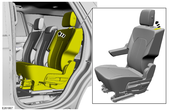
Position the second row seat forward.
-
NOTE:
Long wheelbase shown, short wheelbase similar.
Release the clips and remove the rear scuff plate trim panel.
-
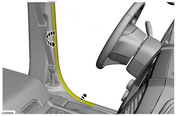
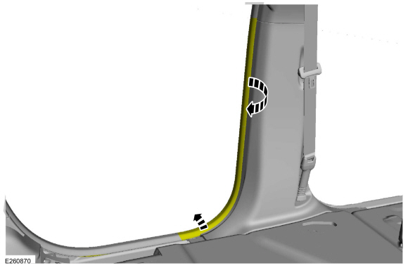
Position the front door weatherstrip aside.
-
Position the rear door weatherstrip aside.
-
Disconnect the front seatbelt retractor from the front seatbelt anchor pretensioner.
-
Press in on the release button
Use the General Equipment: Flat-Bladed Screwdriver
-
Disconnect the front seatbelt retractor.
-
Remove the front seatbelt anchor pretensioner boot.
-
Press in on the sides of the front seatbelt anchor pretensioner boot.
-
Lift up and remove the front seatbelt anchor pretensioner boot.
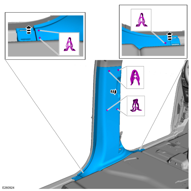
-
Release the clips and remove the lower B-pillar trim panel.
Upper B-Pillar Trim Panel
-
Remove the B-pillar passenger assist handle covers.
Use the General Equipment: Interior Trim Remover
-
Remove the bolts and the B-pillar passenger assist handle.
Torque:
80 lb.in (9 Nm)
-
Remove the upper B-pillar trim panel bolts.
Torque:
36 lb.in (4.1 Nm)
-
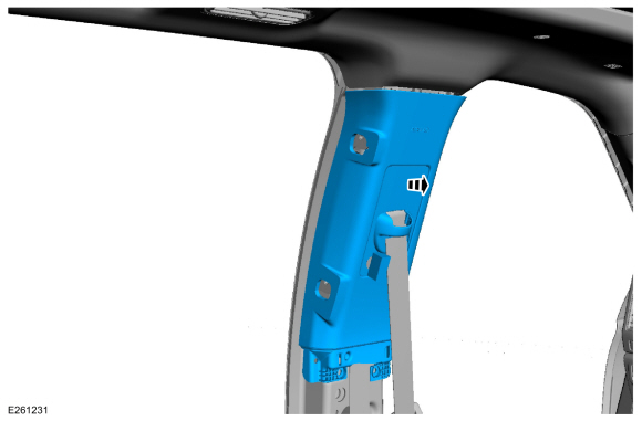
NOTICE:
The upper B-pillar trim panel must be positioned
downward to allow the upper clips to release correctly. Failure to
follow this direction may cause damage to the upper B-pillar trim panel.
Slide the upper B-pillar trim panel down, aligning the clips to the slots in the sheet metal.
-
Remove the upper B-pillar trim panel.
Installation
-
NOTE:
During installation, make sure the seatbelt webbing
is not twisted and the seatbelts and buckles are accessible to the
occupants.
To install, reverse the removal procedure.
-
Check the active restraint system for correct operation.
Refer to: Seatbelt Systems (501-20A Seatbelt Systems, Diagnosis and Testing).
Special Tool(s) /
General Equipment
Interior Trim Remover
Removal
NOTE:
LH shown, RH similar.
NOTE:
Removal steps in this procedure may contain installation details...
Special Tool(s) /
General Equipment
Interior Trim Remover
Removal
NOTE:
Left hand (LH) shown, right hand (RH) similar.
NOTE:
Removal steps in this procedure may contain installation details...
Other information:
Diagnostic Trouble Code (DTC) Chart
Diagnostics in this manual assume a certain skill level and knowledge of Ford-specific diagnostic practices. REFER to: Diagnostic Methods (100-00 General Information, Description and Operation).
Module
DTC
Description
Action
PCM
P0218:00
Transmission Fluid Temperature Sensor 'A' Over Temperature Condition: No Sub Type Information
..
Special Tool(s) /
General Equipment
204-D081A
(204-D081)
Tire Pressure Monitor (TPMS)
Ford Diagnostic Equipment
Programming
NOTE:
The TPMS can be placed into learn mode using a diagnostic scan tool or manually where a diagnostic scan tool is not available.
NOTE:
The horn will sound once and the TPMS
indicator will flash if the training mode has been..


 A-Pillar Trim Panel. Removal and Installation
 C-Pillar Trim Panel. Removal and Installation