Lincoln Navigator: Supplemental Restraint System / Driver Airbag. Removal and Installation
Removal
 WARNING:
The following procedure prescribes critical repair steps
required for correct restraint system operation during a crash. Follow
all notes and steps carefully. Failure to follow step instructions may
result in incorrect operation of the restraint system and increases the
risk of serious personal injury or death in a crash.
WARNING:
The following procedure prescribes critical repair steps
required for correct restraint system operation during a crash. Follow
all notes and steps carefully. Failure to follow step instructions may
result in incorrect operation of the restraint system and increases the
risk of serious personal injury or death in a crash.
-
Refer to: Pyrotechnic Device Health and Safety Precautions (100-00 General Information, Description and Operation).
WARNING:
Before beginning any service procedure in this
manual, refer to health and safety warnings in section 100-00 General
Information. Failure to follow this instruction may result in serious
personal injury.
-
Depower the SRS .
Refer to: Supplemental Restraint System (SRS) Depowering (501-20 Supplemental Restraint System) .
-
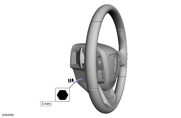
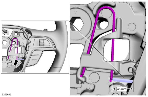
At the side of the steering wheel cover, locate the hole and insert a 3 mm (0.125 inch) hex bit.
 |
-
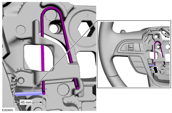
NOTE: The driver airbag has been removed for clarity.
Contact the hex bit to the spring clip.
 |
-
-
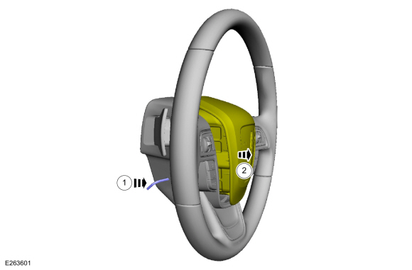
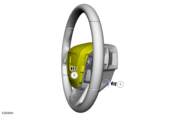
Push in on the hex bit and disengage the spring clip.
-
Pull the driver airbag out and separate it from the steering wheel.
-
Push in on the hex bit and disengage the spring clip.
 |
-
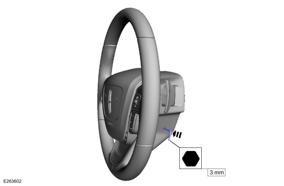
At the side of the steering wheel cover, locate the hole and insert a 3 mm (0.125 inch) hex bit.
 |
-
NOTE: The driver airbag has been removed for clarity.
Contact the hex bit to the spring clip.
 |
-
-
Push in on the hex bit and disengage the spring clip.
-
Pull the driver airbag out and separate it from the steering wheel.
-
Push in on the hex bit and disengage the spring clip.
 |
-
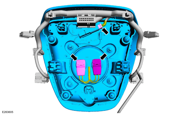
Disconnect the electrical connectors and remove the driver airbag.
 |
Installation
-
Connect the driver airbag electrical connectors.
|
-
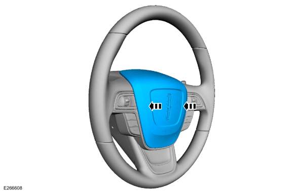
Align the driver airbag to the steering wheel and push
in, engaging the driver airbag retainers to the spring clips.
 |
-
Repower the SRS .
Refer to: Supplemental Restraint System (SRS) Repowering (501-20 Supplemental Restraint System) .
 Clockspring. Removal and Installation
Removal
WARNING:
The following procedure prescribes critical repair steps
required for correct restraint system operation during a crash...
 Front Door Side Impact Sensor. Removal and Installation
Removal
WARNING:
The following procedure prescribes critical repair steps
required for correct restraint system operation during a crash...
Other information:
Lincoln Navigator 2018-2025 Workshop Manual: Exhaust Gas Recirculation (EGR) Temperature Sensor. Removal and Installation
Removal NOTE: Removal steps in this procedure may contain installation details. Remove the engine appearance cover retainers, release the engine appearance cover from the rear retainers and then remove the engine appearance cover...
Lincoln Navigator 2018-2025 Workshop Manual: Turbocharger Oil Supply Tube RH. Removal and Installation
Materials Name Specification Motorcraft® Metal Brake Parts CleanerPM-4-A, PM-4-B, APM-4-C - Removal NOTICE: The turbocharger compressor vanes can be damaged by even the smallest particles. When removing any turbocharger or engine air intake system component, ensure that no debris enters the system...
Categories
- Manuals Home
- 4th Gen Lincoln Navigator Service Manual (2018 - 2025)
- Rear View Mirrors - System Operation and Component Description. Description and Operation
- Power Running Board (PRB). Diagnosis and Testing
- Front Bumper Cover. Removal and Installation
- Transmission Fluid Level Check. General Procedures
- Liftgate Trim Panel. Removal and Installation
Wheel to Hub Runout Minimization. General Procedures
Check
NOTE: Wheel-to-hub optimization is important. Clearance between the wheel and hub can be used to offset or neutralize the Road Force® or run-out of the wheel and tire assembly. For every 0.001 inch of wheel-to-hub clearance, the Road Force® can be affected between 1 and 3 pounds depending on the tire stiffness.
NOTE: The example below illustrates how the clearance between the wheel and the hub can be used to offset the high spot of radial run-out or Road Force®. Following the procedure will make sure of the best optimization.
Position the wheel and tire assembly on the vehicle so that the high spot location of radial run-out or Road Force® is at the 6 o'clock position and