Lincoln Navigator: Anti-Lock Brake System (ABS) and Stability Control / Electric Brake Booster (EBB). Removal and Installation
Removal
NOTE: Removal steps in this procedure may contain installation details.
NOTE: The EBB and the ABS module are serviced as an assembly and should not be separated.
-
NOTE: The PMI process must begin with the current ABS module installed. If the current ABS module does not respond to the diagnostic scan tool, the tool may prompt for As-Built Data as part of the repair.
Using a diagnostic scan tool, begin the PMI process for the ABS module following the onscreen instructions.
-
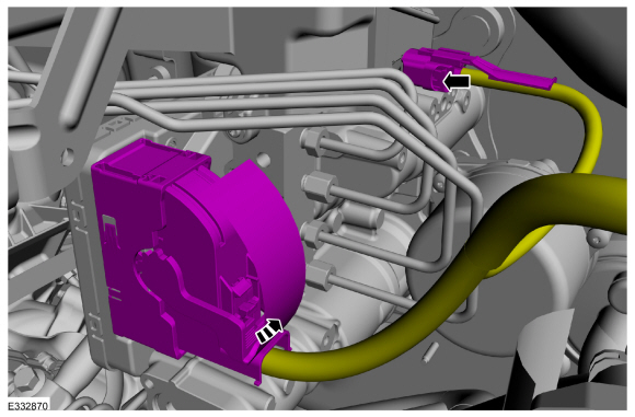
Disconnect the ABS module and brake fluid level sensor electrical connectors.
 |
-
NOTICE: If the brake fluid is spilled on any component, the affected area must be immediately washed down with cold water.
NOTE: Make sure that all openings are sealed.
Disconnect the brake tube fittings.
Torque: 159 lb.in (18 Nm)
 |
-
-
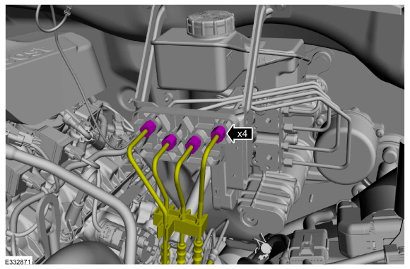
Disconnect the brake tube fittings.
Torque: 159 lb.in (18 Nm)
-
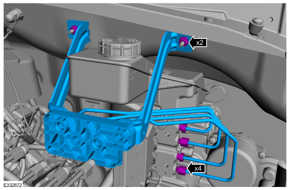
Remove the nuts and the brake tube assembly.
Torque: 97 lb.in (11 Nm)
-
Disconnect the brake tube fittings.
 |
-
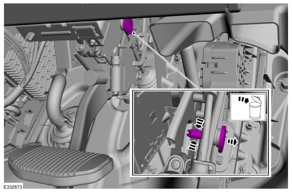
Push inward on the tabs and remove the clevis pin. Discard the pin.
 |
-
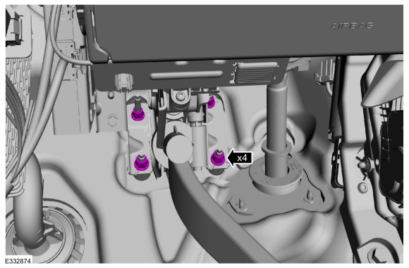
Remove the EBB nuts.
Torque: 17 lb.ft (23 Nm)
 |
-
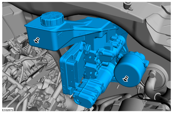
Remove the EBB .
 |
-
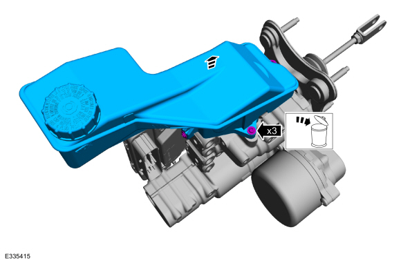
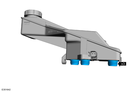
Remove the screws and the brake fluid reservoir. Discard the screws.
 |
-
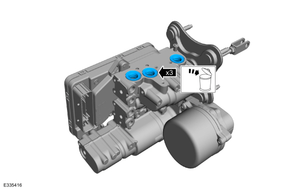
Remove and discard the brake fluid reservoir seals.
 |
Installation
-
Install the new brake fluid reservoir seals on the brake fluid reservoir before installing the reservoir.
 |
-
To install, reverse the removal procedure.
-
Using a diagnostic scan tool, complete the PMI process for the ABS module following the on-screen instructions.
-
Carry out the following service functions using the scan
tool and following the diagnostic scan tool on-screen instructions.
-
Carry out the ABS Brake System Pressure Bleeding and Bleed Check.
-
Carry out the ABS Calibration.
-
Carry out the IVD Initialization.
-
Carry out the EPB initialization.
-
Run the PCM
PATS
programming application and then carry out the Module Initialization
(Parameter Reset) using the scan tool and following the diagnostic scan
tool on-screen instructions.
-
Carry out the ABS Brake System Pressure Bleeding and Bleed Check.
 Anti-Lock Brake System (ABS) and Stability Control. Diagnosis and Testing
Diagnostic Trouble Code (DTC) Chart
Diagnostics in this manual assume a certain skill level and knowledge of Ford-specific diagnostic practices. REFER to: Diagnostic Methods (100-00 General Information, Description and Operation)...
 Front Wheel Speed Sensor. Removal and Installation
Materials
Name
Specification
Motorcraft® Metal Brake Parts CleanerPM-4-A, PM-4-B, APM-4-C
-
Removal
NOTE:
Removal steps in this procedure may contain installation details...
Other information:
Lincoln Navigator 2018-2025 Workshop Manual: Piston Selection. General Procedures
Check Refer to specifications for piston selection. Refer to: Specifications (303-01) . NOTE: The cylinder bore must be within the specifications for taper and out-of-round before fitting a piston. Measure the cylinder bore in 2 directions...
Lincoln Navigator 2018-2025 Workshop Manual: High-Pressure Fuel Pump. Removal and Installation
Removal NOTICE: Do not loosen any fittings or plugs on the high-pressure fuel pump. With the vehicle in NEUTRAL, position it on a hoist. Refer to: Jacking and Lifting (100-02 Jacking and Lifting, Description and Operation). Remove the engine appearance cover retainers, release the engine appearance cover from the rear retaining tabs on the inta..
Categories
- Manuals Home
- 4th Gen Lincoln Navigator Service Manual (2018 - 2025)
- Transmission Fluid Level Check. General Procedures
- Rear View Mirrors - System Operation and Component Description. Description and Operation
- SYNC Module [APIM]. Removal and Installation
- Front Bumper. Removal and Installation
- Front Bumper Cover. Removal and Installation
Rear Stabilizer Bar Link. Removal and Installation
Removal
NOTE: Removal steps in this procedure may contain installation details.
With the vehicle in NEUTRAL, position it on a hoist.Refer to: Jacking and Lifting (100-02 Jacking and Lifting, Description and Operation).
NOTE: Use the hex-holding feature to prevent the stud from turning while removing the nut.
Remove and discard the 2 rear stabilizer bar link nuts and remove the rear stabilizer bar link.Torque: 46 lb.ft (63 Nm)
