Lincoln Navigator: Engine Emission Control - 3.5L EcoBoost (272kW/370PS) / Engine Emission Control - Component Location. Description and Operation
| Item | Description |
|---|---|
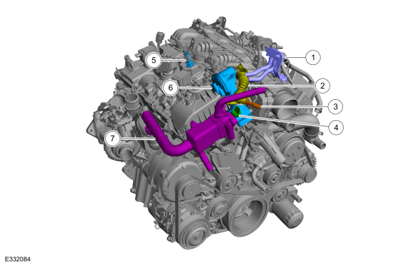
| 1 | Differential pressure feedback EGR sensor. |
| 2 | EGR outlet tube. |
| 3 | EGR temperature sensor. |
| 4 | EGR back pressure sensor. |
| 5 | PCV valve. |
| 6 | EGR valve. |
| 7 | EGR cooler. |

 Engine Emission Control - System Operation and Component Description. Description and Operation
System Operation
Exhaust Gas Recirculation (EGR) System
Overview
The EGR system controls the NOX
emissions. Small amounts of exhaust gases are recirculated back into
the combustion chamber to mix with the air to fuel charge...
Other information:
Lincoln Navigator 2018-2026 Workshop Manual: Cooling Fan Motor and Shroud. Removal and Installation
Removal With the vehicle in NEUTRAL, position it on a hoist. Refer to: Jacking and Lifting (100-02 Jacking and Lifting, Description and Operation). Remove the air cleaner outlet pipe. Refer to: Air Cleaner Outlet Pipe (303-12) ...
Lincoln Navigator 2018-2026 Workshop Manual: Front Door Trim Panel. Removal and Installation
Special Tool(s) / General Equipment Pick Hook Interior Trim Remover Removal Release the clip and remove the sail panel trim panel. If equipped. Disconnect the front door tweeter speaker electrical connector...
Categories
- Manuals Home
- 4th Gen Lincoln Navigator Service Manual (2018 - 2026)
- Body Control Module (BCM). Removal and Installation
- Remote Function Actuator (RFA) Module. Removal and Installation
- Brake Service Mode Activation and Deactivation. General Procedures
- Head Up Display (HUD) Module Calibration. General Procedures
- SYNC Module [APIM]. Removal and Installation
Rear Drive Halfshafts. Diagnosis and Testing
Preliminary Inspection
Visually inspect the CV joints, housing, boots, and clamps for obvious signs of mechanical damage.If an obvious cause for an observed or reported concern is found, correct the cause (if possible) before proceeding to the next step
If the cause is not visually evident, verify the symptom and REFER to Symptom Chart: NVH.