Lincoln Navigator: Supplemental Restraint System / Front Impact Severity Sensor. Removal and Installation
Removal
 WARNING:
The following procedure prescribes critical repair steps
required for correct restraint system operation during a crash. Follow
all notes and steps carefully. Failure to follow step instructions may
result in incorrect operation of the restraint system and increases the
risk of serious personal injury or death in a crash.
WARNING:
The following procedure prescribes critical repair steps
required for correct restraint system operation during a crash. Follow
all notes and steps carefully. Failure to follow step instructions may
result in incorrect operation of the restraint system and increases the
risk of serious personal injury or death in a crash.
NOTE: Removal steps in this procedure may contain installation details.
-
Refer to: Pyrotechnic Device Health and Safety Precautions (100-00 General Information, Description and Operation).
WARNING:
Before beginning any service procedure in this
manual, refer to health and safety warnings in section 100-00 General
Information. Failure to follow this instruction may result in serious
personal injury.
-
With the vehicle in NEUTRAL, position it on a hoist.
Refer to: Jacking and Lifting (100-02 Jacking and Lifting, Description and Operation).
-
Depower the SRS .
Refer to: Supplemental Restraint System (SRS) Depowering (501-20 Supplemental Restraint System) .
-
-
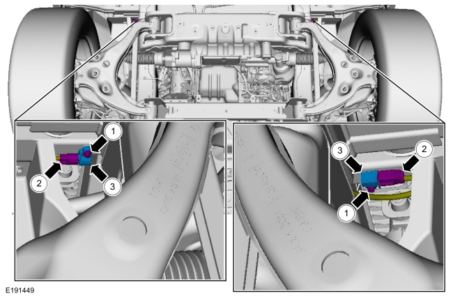
Remove the bolt.
Torque: 119 lb.in (13.5 Nm)
-
Disconnect the electrical connector.
-
Remove the front impact severity sensor.
-
Remove the bolt.
 |
Installation
-
NOTE: The front impact severity sensor mating surfaces must be smooth and allow for a flush attachment to each other.
To install, reverse the removal procedure.
-
Repower the SRS .
Refer to: Supplemental Restraint System (SRS) Repowering (501-20 Supplemental Restraint System) .
 Front Door Side Impact Sensor. Removal and Installation
Removal
WARNING:
The following procedure prescribes critical repair steps
required for correct restraint system operation during a crash...
 Occupant Classification System (OCS) Sensor. Removal and Installation
Special Tool(s) /
General Equipment
Flat Headed Screw Driver
Interior Trim Remover
Removal
WARNING:
The following procedure prescribes critical repair steps
required for correct restraint system operation during a crash...
Other information:
Lincoln Navigator 2018-2025 Workshop Manual: Roof Panel. Removal and Installation
Special Tool(s) / General Equipment 6.5 mm Drill Bit Grinder Self-Piercing Rivet (SPR) Remover/Installer Belt Sander Knife Locking Pliers Materials Name Specification Metal Bonding AdhesiveTA-1, TA-1-B, 3M™ 08115, LORD Fusor® 108B, Henkel Teroson EP 5055 - Roof Ditch Sealer3M™ 08307, LORD Fusor® 129 ..
Lincoln Navigator 2018-2025 Workshop Manual: Front Cover to Coolant Pipe Seal. Removal and Installation
Special Tool(s) / General Equipment 303-1528Remover/Installer, Water Tube Seal Removal NOTICE: During engine repair procedures, cleanliness is extremely important. Any foreign material, including any material created while cleaning gasket surfaces that enters the oil passages, coolant passages or the oil pan, may cause engine failure. Remove the..
Categories
- Manuals Home
- 4th Gen Lincoln Navigator Service Manual (2018 - 2025)
- Windshield Washer Pump. Removal and Installation
- Service Information
- All Terrain Control Module (ATCM). Removal and Installation
- Body Control Module (BCM). Removal and Installation
- Front Bumper Cover. Removal and Installation
Rear Stabilizer Bar Link. Removal and Installation
Removal
NOTE: Removal steps in this procedure may contain installation details.
With the vehicle in NEUTRAL, position it on a hoist.Refer to: Jacking and Lifting (100-02 Jacking and Lifting, Description and Operation).
NOTE: Use the hex-holding feature to prevent the stud from turning while removing the nut.
Remove and discard the 2 rear stabilizer bar link nuts and remove the rear stabilizer bar link.Torque: 46 lb.ft (63 Nm)
