Lincoln Navigator: Front Seats / Front Seat Power Lumbar Assembly - Vehicles With: Multi-Contour Seats. Removal and Installation
Special Tool(s) / General Equipment
| Interior Trim Remover |
Removal
NOTE: Driver seat shown, passenger seat similar.
NOTE: The front seat backrest driver seat SCMG (driver multi-contour seat module)/SCMH (passenger multi-contour seat module) is part of the front seat power lumbar assembly and is serviced as an assembly.
-
NOTE: This step is necessary only when installing a new component.
NOTE: The PMI (programmable module installation) process must begin with the current SCMG (driver multi-contour seat module)/SCMH (passenger multi-contour seat module) installed. If the current SCMG (driver multi-contour seat module)/SCMH (passenger multi-contour seat module) does not respond to the diagnostic scan tool, the tool may prompt for As-Built Data as part of the repair.
Using a diagnostic scan tool, begin the PMI process for the SCMG / SCMH following the on-screen instructions.
-
Remove the front seat.
Refer to: Front Seat (501-10A Front Seats, Removal and Installation).
-
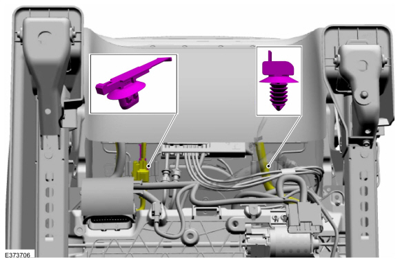
Release the front seat wiring harness and electrical
connector retainers and position the front seat wiring harnesses aside.
 |
-
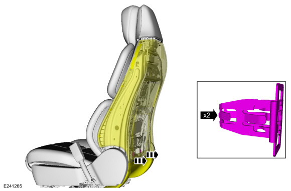
Release the front seat back panel straps and position the front seat back panel aside.
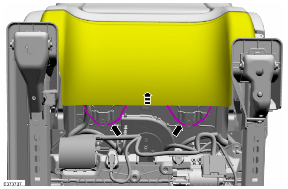 |
-
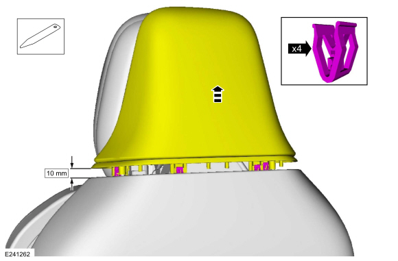
NOTICE: The back panel finish can be easily marred or torn, use care when working around it.
Raise and partially separate the head restraint rear cover enough to disengage the clips from the back panel.
Use the General Equipment: Interior Trim Remover
 |
-
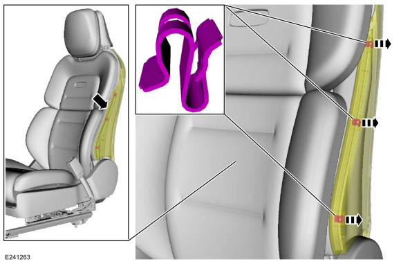
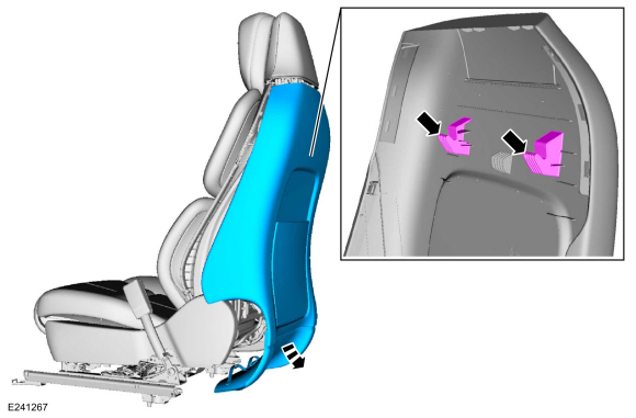
On both sides, grasp the back panel where it meets the
module trim, pull to release the clips and separate the back panel from
the module trim.
 |
-
On both sides, using the interior trim remover, place it
in between the plastic substrate and the clip, pry and detach the
module clips from the back panel windows.
Use the General Equipment: Interior Trim Remover
-
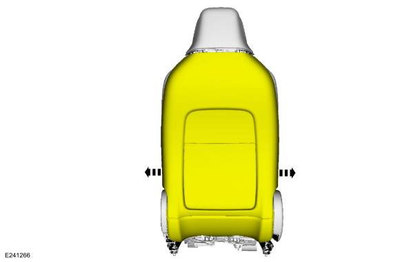
Pull out at the bottom, release the clips and detach the back panel from the backrest frame.
 |
-
Pull out at the sides of the back panel.
 |
-
Pull down and out and remove the back panel.
 |
-
If equipped with video display.
Remove the video display.
Refer to: Information and Entertainment System - Component Location (415-00 Information and Entertainment System - General Information - Vehicles With: SYNC 4, Description and Operation).
-
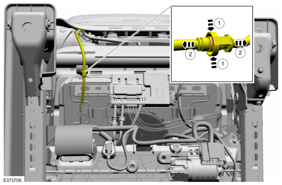
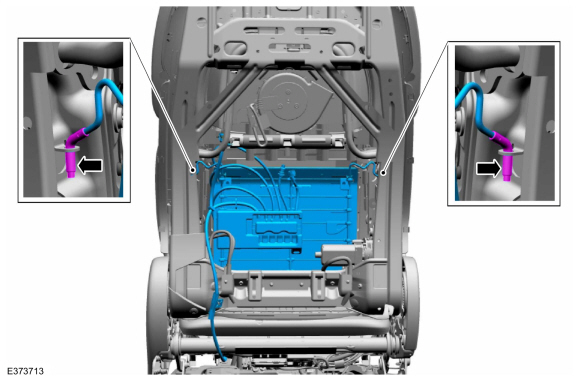
Disconnect the front seat power lumbar assembly hose.
-
Compress/squeeze the hose end fitting.
-
Disconnect the hose.
-
Compress/squeeze the hose end fitting.
 |
-
-
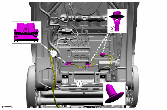
Detach the front seat power lumbar assembly hose retainer.
-
Detach the SCMG / SCMH wiring harness retainers.
-
Disconnect the SCMG / SCMH electrical connector.
-
Detach the front seat power lumbar assembly hose retainer.
 |
-
-
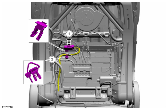
Detach and disconnect the front seat power lumbar assembly electrical connector.
-
Detach the front seat backrest heater mat electrical connector.
-
Detach and disconnect the front seat power lumbar assembly electrical connector.
 |
-
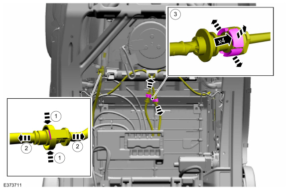
Disconnect the front seat power lumbar assembly hoses.
-
Compress/squeeze the hose end fitting.
-
Disconnect the hose.
-
Release the coupling retainers and separate the front seat backrest bolster hoses from the SCMG / SCMH .
-
Compress/squeeze the hose end fitting.
 |
-
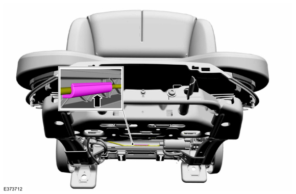
Detach the front seat power lumbar assembly from the front seat backrest lower retainer.
 |
-
Detach the J-hooks and remove front seat power lumbar assembly.
 |
Installation
-
To install, reverse the removal procedure.
-
NOTE: This step is only necessary when installing a new component.
Using a diagnostic scan tool, complete the PMI process for the SCMG / SCMH following the on-screen instructions.
 Front Seat Cushion Cover. Removal and Installation
Special Tool(s) /
General Equipment
Interior Trim Remover
Removal
Passenger seat
Remove the OCS .
Refer to: Occupant Classification System (OCS) Sensor (501-20B Supplemental Restraint System, Removal and Installation)...
 Front Seat Track. Removal and Installation
Removal
NOTE:
Removal steps in this procedure may contain installation details.
Remove the front seat backrest.
Refer to: Front Seat Backrest (501-10A Front Seats, Removal and Installation)...
Other information:
Lincoln Navigator 2018-2024 Workshop Manual: Powertrain/Drivetrain Mount Neutralizing. General Procedures
Adjustment NOTE: Refer to the appropriate section and procedure for special instructions on loosening and tightening mount fasteners. With the vehicle in NEUTRAL, position it on a hoist. Refer to: Jacking and Lifting (100-02 Jacking and Lifting, Description and Operation)...
Lincoln Navigator 2018-2024 Workshop Manual: Rear Halfshaft Seal. Removal and Installation
Special Tool(s) / General Equipment 205-907Handle, 32 DriverTKIT-2008DH-FLM 206-034 (T88P-20202-B) Installer, Wheel Speed Sensor RingTKIT-1988-FLMTKIT-1988-LM Feeler Gauge Removal NOTE: Removal steps in this procedure may contain installation details...
Categories
- Manuals Home
- 4th Gen Lincoln Navigator Service Manual (2018 - 2024)
- Power Running Board (PRB). Diagnosis and Testing
- Front Bumper Cover. Removal and Installation
- SYNC Module [APIM]. Removal and Installation
- Rear Suspension Height Sensor. Removal and Installation
- Rear View Mirrors - System Operation and Component Description. Description and Operation
Diagnostic Methods. Description and Operation
This document provides critical diagnostic knowledge required for successful repair outcomes. It identifies technical competencies expected by users of this manual.
Ford Diagnostic Assumptions
Ford diagnostics assume the vehicle concern described by the test title is currently present. Exceptions to this rule are noted in each test. Do not replace modules or other components as directed by a diagnostic if the concern is not present at the time of testing.