Lincoln Navigator: Automatic Transmission - 10-Speed Automatic Transmission – 10R80 / Main Control Valve Body. Removal and Installation
Removal
NOTE: The Solenoid Body Strategy Data Download procedure must be performed if a new main control valve body is installed.
NOTE: If a main control valve body overhaul is carried out or a new SS is installed, carry out the adaptive learning drive cycle procedure at the end of the repair.
-
Remove the transmission fluid pan gasket and filter.
Refer to: Transmission Fluid Pan, Gasket and Filter (307-01 Automatic Transmission - 10-Speed Automatic Transmission – 10R80, Removal and Installation).
-
Place the vehicle in emergency park position release.
Refer to: Emergency Park Position Release (307-05 Automatic Transmission External Controls, General Procedures).
-
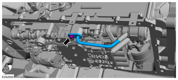
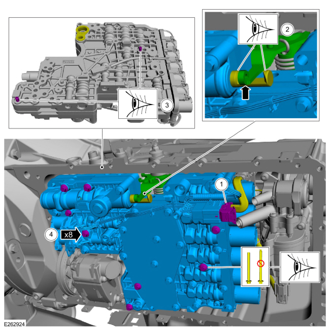
Remove the bolt and the transmission fluid auxiliary pump tube.
 |
-
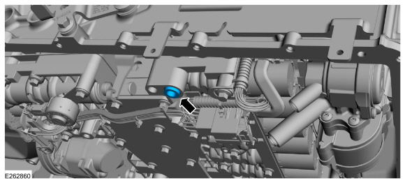
Remove the transmission fluid auxiliary pump tube seal.
 |
-
NOTE: The internal wiring harness electrical connector can not be fully disconnected until lowering the main control valve body.
Unlock the internal wiring harness electrical connector.
 |
-
Remove the main control valve body.
-
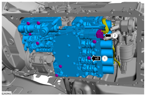
While supporting the main control valve body, remove the main control-to-transmission case bolts.
-
Disconnect the internal wiring harness electrical connector while removing the main control valve body.
-
While supporting the main control valve body, remove the main control-to-transmission case bolts.
 |
-
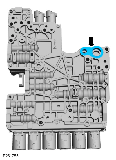
Remove the main control assembly to transmission fluid pump seal.
 |
Installation
-
Install the main control assembly to transmission fluid pump seal.
|
-
NOTICE: Do not install a 71 mm length bolt in the location shown or the transmission clutch and planetary container will be damaged and result in transmission failure.
Loosely install the main control valve body.
-
Connect the internal wiring harness electrical connector while installing the main control valve body.
-
Align the TR sensor with the park pawl lock valve.
-
Align the guide pins on the main control valve body with the alignment holes in the transmission case.
-
Loosely install the 68 mm length main control-to-transmission case bolts.
-
Connect the internal wiring harness electrical connector while installing the main control valve body.
 |
-
Lock the internal wiring harness electrical connector.
|
-
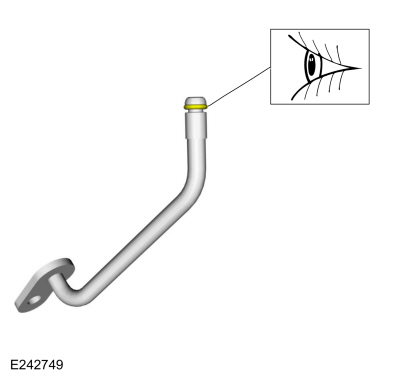
Install the transmission fluid auxiliary pump tube seal.
|
-
Inspect the transmission fluid auxiliary pump tube O-ring.
 |
-
Install the transmission fluid auxiliary pump tube and loosely install the bolt.
|
-
-
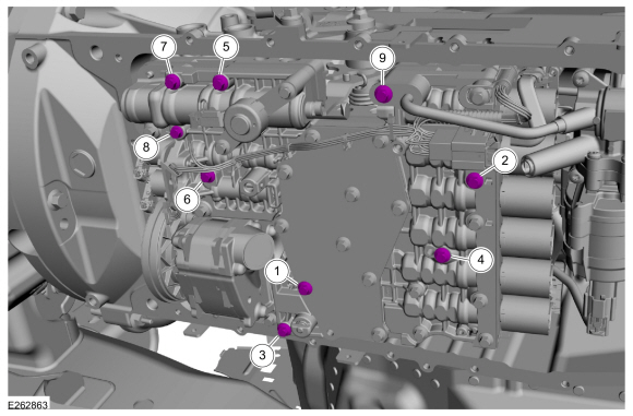
Tighten the bolts No. 1-8 in the sequence shown.
Torque: 89 lb.in (10 Nm)
-
Tighten bolt No. 9
Torque: 106 lb.in (12 Nm)
-
Tighten the bolts No. 1-8 in the sequence shown.
 |
-
Install the transmission fluid pan gasket and filter.
Refer to: Transmission Fluid Pan, Gasket and Filter (307-01 Automatic Transmission - 10-Speed Automatic Transmission – 10R80, Removal and Installation).
-
NOTICE: When the repair is complete, the park overide lever must be returned to the NORMAL OPERATING POSITION or vehicle damage can occur.
Return the park override lever to the normal operating position.
Refer to: Emergency Park Position Release (307-05 Automatic Transmission External Controls, General Procedures).
-
NOTE: The solenoid body strategy data file and solenoid body identification must be updated anytime a new main control valve body is installed. A new main control valve body service tag must be installed over the current main control valve body service tag on the transmission case.
If a new main control valve body was installed, download a new transmission strategy.
Refer to: Transmission Strategy Download (307-01 Automatic Transmission - 10-Speed Automatic Transmission – 10R80, General Procedures).
-
If a main control valve body overhaul was carried out or a new SS was
installed, carry out the adaptive learning drive cycle procedure.
Refer to: Adaptive Learning Drive Cycle (307-01 Automatic Transmission - 10-Speed Automatic Transmission – 10R80, General Procedures).

 Intermediate Speed Sensor A (ISSA). Removal and Installation
Removal
Remove the main control valve body.
Refer to: Main Control Valve Body (307-01 Automatic Transmission -
10-Speed Automatic Transmission – 10R80, Removal and Installation)...
Other information:
Lincoln Navigator 2018-2026 Workshop Manual: Bodyside Moulding. Removal and Installation
Removal NOTE: Removal steps in this procedure may contain installation details. NOTE: LWB (long wheel base) shown, SWB (short wheel base) similar. NOTE: RH side views shown, LH side similar. Using a non-marring trim tool, detach the push pin retainers and remove the bodyside moulding...
Lincoln Navigator 2018-2026 Workshop Manual: Voice Microphone. Removal and Installation
Removal Vehicles equipped with dual voice microphones Lower the headliner. Refer to: Headliner - Lowering (501-05 Interior Trim and Ornamentation, Removal and Installation). Disconnect the electrical connector...
Categories
- Manuals Home
- 4th Gen Lincoln Navigator Service Manual (2018 - 2026)
- Power Running Board (PRB). Diagnosis and Testing
- Body and Paint
- Brake Service Mode Activation and Deactivation. General Procedures
- Windshield Washer Pump. Removal and Installation
- Vehicle Dynamics Control Module (VDM). Removal and Installation
Diagnostic Methods. Description and Operation
This document provides critical diagnostic knowledge required for successful repair outcomes. It identifies technical competencies expected by users of this manual.
Ford Diagnostic Assumptions
Ford diagnostics assume the vehicle concern described by the test title is currently present. Exceptions to this rule are noted in each test. Do not replace modules or other components as directed by a diagnostic if the concern is not present at the time of testing.