Lincoln Navigator: Instrumentation, Message Center and Warning Chimes / Message Center - System Operation and Component Description. Description and Operation
System Operation
System Diagram
Message Center
*.sttxt { visibility: hidden; } *.stcallout { visibility: visible; } 1 Parking Brake Switch 2 Brake Fluid Level Switch 3 Door/Liftgate Ajar Switches 4 Hood Ajar Switch 5 Front/Rear Seatbelt Buckle Switches 6 RH Steering Wheel Switch 7 PCM 8 TCCM 9 ABS Module 10 PSCM 11 HCM 12 VDM 13 IPMA 14 SODx 15 CCM 16 BCM 17 RCM 18 SCCM 19 FCIM 20 DSM 21 RBM 22 APIM 23 TRM 24 GWM 25 Fuel Pump and Sender Unit 26 IPC 27 Message Center Display E367346| Item | Description |
|---|---|
| 1 | Parking brake switch |
| 2 | Brake fluid level switch |
| 3 | Door/liftgate ajar switches |
| 4 | Hood ajar switch |
| 5 | Front/rear seatbelt buckle switches |
| 6 | RH steering wheel switch |
| 7 | PCM |
| 8 | TCCM |
| 9 | ABS module |
| 10 | PSCM |
| 11 | HCM |
| 12 | VDM |
| 13 | IPMA |
| 14 | Side Obstacle Detection Control Module x (SODx) |
| 15 | CCM |
| 16 | BCM |
| 17 | RCM |
| 18 | SCCM |
| 19 | FCIM |
| 20 | DSM |
| 21 | RBM |
| 22 | APIM |
| 23 | TRM |
| 24 | GWM |
| 25 | Fuel pump and sender unit |
| 26 | IPC |
| 27 | Message center display |
Network Message Chart - Displays
The data in each display is shown when the IPC receives messaged inputs from other modules on the CAN , unless the display data is controlled exclusively by the IPC . The IPC communicates on the HS-CAN3 . If the originating module communicates on a network other than the HS-CAN3 , the messaged signals are sent to the GWM first, then to the IPC .
| Display | Network Message | Originating Module | Originating CAN | Receiving Module |
|---|---|---|---|---|
| Adaptive cruise control | Cruise control set speed display | PCM | FD-CAN | IPC |
|
IPMA | |||
| Compass | Compass direction | APIM | HS-CAN3 | IPC |
| Digital speedometer | Vehicle speed | PCM | FD-CAN | IPC |
| DTE /Average fuel economy | Fuel level data | IPC | HS-CAN3 | PCM |
|
PCM | FD-CAN | IPC | |
| Transport mode | BCM | HS-CAN1 | IPC | |
| Drive mode (Normal, Normal 4x4 Auto, Excite, Conserve, Slippery, Deep Conditions, Deep Sand, Slow Climb) |
|
ABS module | FD-CAN | IPC |
| Selectable AWD mode status | TCCM | FD-CAN | IPC | |
| Forward collision alert | Forward collision warning indicator request | IPMA | FD-CAN | IPC |
| Lane keeping system |
|
IPMA | FD-CAN | IPC |
| Lane centering aid system |
|
IPMA | FD-CAN | IPC |
| Navigation | Navigation data | APIM | HS-CAN3 | IPC |
| Odometer | Odometer count | PCM | FD-CAN | IPC |
| Off road (displays with Deep Sand and Slow Climb selections) |
|
ABS module | FD-CAN | IPC |
| Steering wheel angle | PSCM | |||
| Outside air temperature | Ambient air temperature filtered | PCM | FD-CAN | HVAC module |
| Outside air temperature status | FCIM | MS-CAN | IPC | |
| PRND |
|
PCM | FD-CAN | IPC |
|
BCM | HS-CAN1 |
Network Message Chart - Information-On-Demand Displays
The information-on-demand displays are selected using the menu screens in the message center. The data in each display is shown when the IPC receives messaged inputs from other modules on the CAN , unless the display data is controlled exclusively by the IPC . The IPC communicates on the HS-CAN3 . If the originating module communicates on a network other than the HS-CAN3 , the messaged signals are sent to the GWM first, then to the IPC .
| Information Display | Network Message | Originating Module | Originating CAN | Receiving Module |
|---|---|---|---|---|
| Engine oil life | Engine oil life | PCM | FD-CAN | IPC |
| Engine oil life reset | IPC | HS-CAN3 | PCM | |
| Seatbelts (Including rear seatbelts) |
|
RCM | HS-CAN2 | IPC |
| TPMS |
|
BCM | HS-CAN1 | IPC |
| Trailer lighting | Parklamp status | BCM | HS-CAN1 | IPC |
|
TRM | HS-CAN3 | IPC | |
| Trailer information |
|
IPMA | FD-CAN | IPC |
|
IPMA | FD-CAN | IPC | |
|
PCM | FD-CAN | IPC | |
| Ignition status | BCM | HS-CAN1 | IPC |
Network Message Chart - Warning Messages
A warning message is displayed in the message center when the IPC receives messaged inputs from other modules on the CAN , unless the message is for a function exclusive to the IPC . The IPC communicates on the HS-CAN3 . If the originating module communicates on a network other than the HS-CAN3 , the messaged signals are sent to the GWM first, then to the IPC .
| IPC Message | Network Message | Originating Module | Originating CAN | Receiving Module |
|---|---|---|---|---|
| 4WD fault and shift instructions | 4WD high/low status | TCCM | FD-CAN | IPC |
| Adaptive cruise control |
|
IPMA | FD-CAN | IPC |
| Adaptive headlamps | Adaptive headlamp fault | HCM | FD-CAN | IPC |
| Auto hold | Auto hold message request | ABS module | FD-CAN | IPC |
| Auto stop start | Stop start message request | PCM | FD-CAN | IPC |
| Automatic engine shutdown | Engine idle shutdown status | PCM | FD-CAN | IPC |
| BLIS / CTA |
|
IPMA | FD-CAN | IPC |
|
||||
| Brake system/Parking brake engaged/Brake fluid low |
|
ABS module | FD-CAN | IPC |
| Brake fluid level status | ABS module | FD-CAN | BCM | |
| Brake warning indicator request (brake fluid level) | BCM | HS-CAN1 | IPC | |
| Brake applied - power reduced | Brake pedal applied message request | PCM | FD-CAN | IPC |
| Change 4WD lubrication | AWD status message request | TCCM | FD-CAN | IPC |
| Check fuel fill inlet | Fuel fill inlet message display | PCM | FD-CAN | IPC |
| Door/hood/liftgate ajar |
|
BCM | HS-CAN1 | IPC |
| Drive control - vehicle dynamic suspension | Vehicle dynamics fault | VDM | FD-CAN | IPC |
| Drive mode | Selective drive mode message request | ABS module | FD-CAN | IPC |
| Driver monitor (camera) | Driver monitor camera message request | IPMA | FD-CAN | IPC |
| Electric parking brake | Parking brake message request | ABS module | FD-CAN | IPC |
| Electronic locking differential (eLocker) | Rear differential lock message request | PCM | FD-CAN | IPC |
| Engine oil level | Engine oil level warning request | PCM | FD-CAN | IPC |
| Engine oil change minder | Engine oil life | PCM | FD-CAN | IPC |
| Engine on | Driver door ajar status | BCM | HS-CAN1 | IPC |
|
PCM | FD-CAN | ||
| Factory/transport mode |
|
BCM | HS-CAN1 | IPC |
| Front camera | Camera status display | IPMA | FD-CAN | IPC |
| Hill descent control | Hill descent message request | ABS module | FD-CAN | IPC |
| Keypad code | Keypad factory code | BCM | HS-CAN1 | IPC |
| Lane centering aid | Traffic jam assist message request | IPMA | FD-CAN | IPC |
| Lane keeping system |
|
IPMA | FD-CAN | IPC |
| Load shed (12-volt battery) | Power shed level request | BCM | HS-CAN1 | IPC |
| Low key fob battery | Lock system message request | BCM | HS-CAN1 | IPC |
| Memory seat | Memory command | DSM | MS-CAN | IPC |
| Neutral tow | AWD status message request | TCCM | FD-CAN | IPC |
| Off road mode | AWD status message request | TCCM | FD-CAN | IPC |
| Parking aid/autopark | Parking aid fault status | IPMA | FD-CAN | IPC |
| Passive key and immobilizer system | Immobilizer message display | BCM | HS-CAN1 | IPC |
| Power pack status | PCM | FD-CAN | ||
| Perimeter alarm | Perimeter alarm chime request | BCM | HS-CAN1 | IPC |
| Power child door locks | Lock system message request | BCM | HS-CAN1 | IPC |
| Power running boards | Power step message request | RBM | MS-CAN | IPC |
| Power steering | EPAS failure | PSCM | FD-CAN | IPC |
| Powertrain cooling | Powertrain cooling message request | PCM | FD-CAN | IPC |
| Pre-collision assist | Forward collision warning message request | IPMA | FD-CAN | IPC |
| Remote start | Remote start status | BCM | HS-CAN1 | IPC |
| Reverse brake assist |
|
IPMA | FD-CAN | IPC |
| Rear seatbelt monitor |
|
RCM | HS-CAN2 | IPC |
| Seatbelt (Buckle up) | Driver seatbelt buckle status | RCM | HS-CAN2 | IPC |
| Service AdvanceTrac | Stability-traction control chime request | ABS module | FD-CAN | IPC |
| Side wind compensation | Stability-traction control mode message request | ABS module | FD-CAN | IPC |
| Speed sign recognition | Traffic sign recognition message request | IPMA | FD-CAN | IPC |
| Stability-traction control on/off | Stability-traction control on/off message request | ABS module | FD-CAN | IPC |
| Starting system | Starting system message request | PCM | FD-CAN | IPC |
| Steering wheel lock | Steering wheel lock message request | BCM | HS-CAN1 | IPC |
| TPMS (fault and tire training status) | Tire pressure system status | BCM | HS-CAN1 | IPC |
| Trailer Information (trailer lighting, trailer brake, trailer sway) | Trailer sway event in progress | ABS module | FD-CAN | IPC |
|
TRM | HS-CAN3 | IPC | |
| Trailer display (trailer backup assist) |
|
IPMA | FD-CAN | IPC |
| Transmission | Transmission message request | PCM | FD-CAN | IPC |
| Transmission not in P |
|
PCM | FD-CAN | IPC |
|
BCM | HS-CAN1 | ||
| Vehicle start inhibit (Over the Air [OTA] updates) | Vehicle start inhibit message display | GWM | HS-CAN3 | IPC |
Displays
Adaptive Cruise Control
The message center provides a display showing the ACC gap setting, set speed and a graphical image of a vehicle from behind. The stop and go feature (part of the ACC ) provides message displays to indicate the vehicle is stopped and to press resume to engage the cruise control again.
Calm Screen
The message center provides a selectable instrument cluster screen option with a limited number of displays. The displays include digital speedometer, outside air temperature, clock, pop-up warning messages and forward collision warnings and indicators.
Compass
The compass direction is displayed as a 1 or 2 character display in the message center that indicates the current direction of the vehicle (N, NE, E, SE, S, SW, W, or NW).
Digital Speedometer
The IPC
provides a redundant digital speedometer display in the message
center. The digital speedometer display operates using the same vehicle
speed inputs used to control the speedometer gauge. See Speedometer.
Refer
to: Instrument Panel Cluster (IPC) - System Operation and Component
Description (413-01 Instrumentation, Message Center and Warning Chimes,
Description and Operation).
DTE /Average Fuel Economy
The DTE is calculated in the PCM using the Running Average Fuel Economy (RAFE), which is the fuel economy up to 400 km (250 miles), and the fuel level input from the fuel sender to determine how many kilometers (miles) the vehicle can be driven based on the remaining fuel in the tank. The DTE displayed value can increase, or decrease, or stay the same value depending on customer driving patterns.
The Running Average Fuel Economy (RAFE) is not transmitted over the CAN , however the IPC will show an invalid Running Average Fuel Economy (RAFE) value in Engineering Test Mode. The DTE can vary in the short term by up to 80 km (50 miles), but is usually within 16 km (10 miles). Even if the fuel economy is relatively constant, the DTE can be off over a 80 km (50 mile) range by -24% to +38%.
The DTE display and the fuel gauge both use the fuel level input from the fuel tank and engine fuel consumption to provide their respective functions. If the fuel gauge doesn't function correctly, both the fuel gauge and the DTE display are affected.
If the DTE does not function correctly and the fuel gauge is correct, then Running Average Fuel Economy (RAFE), odometer or vehicle speed related input can be invalid.
The PCM defaults to a preset baseline L/100km (mpg) when the keep alive memory is reset or PCM is flashed and changes afterward based on driving habits and conditions.
NOTE: The customer calculated DTE can be higher or lower than the DTE displayed in the message center due to changes in driving conditions. It is important to understand how the DTE is calculated and the factors that impact the DTE display when determining how to address any DTE concerns.
Since the DTE is calculated and averaged over a longer period of time (400 km [250 miles]), varying driving conditions can have a significant impact on the current or short term DTE as opposed to the displayed DTE . This difference often leads to customer complaints of incorrect or invalid DTE . The following list provides some (not all) of the driving conditions that may lead to an incorrect or fluctuating DTE concern:
- Changing between towing/not towing.
- Changing driving between city and highway.
- Allowing the vehicle to idle for long periods of time.
- Using the remote start feature frequently to allow the vehicle to warm up, particularly when parked on a grade.
- Parking or driving on grades.
- Inconsistent use of gasoline or E85 fuels.
- Over-fueling or not filling the tank completely (trickle filling at above full, partial filling with less than 10% of tank capacity).
The PCM uses the following network messages to control the DTE .
- Fuel alcohol percent
- Fuel flow volume display
- Odometer count
- Transport mode
- Fuel level input from the IPC
Drive Mode - Normal, Normal 4x4 Auto, Excite, Conserve, Slippery, Deep Conditions; Deep Sand, Slow Climb (Off Road)
The IPC provides a drive mode RTT
indicator in text form when a specific drive mode is selected. When
Deep Sand or Slow Climb drive modes are selected, vehicle pitch, roll
and steering angle indication also displays. For additional information
on the drive mode feature,
Refer to: Anti-Lock Brake System (ABS)
and Stability Control - System Operation and Component Description
(206-09 Anti-Lock Brake System (ABS) and Stability Control, Description
and Operation).
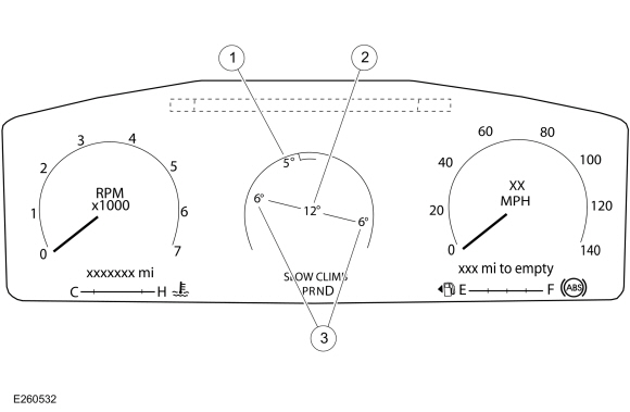
| Item | Description |
|---|---|
| 1 | Pitch indication (in degrees) |
| 2 | Steering angle (in degrees) |
| 3 | Roll indication (in degrees) |
Forward Collision Alert
The message center provides a forward collision alert display when a possible forward collision is detected due to a short following distance to the vehicle in front and little or no driver intervention is detected.
Lane Centering Aid System
The lane centering aid system is part of the advanced driver assist system. The lane centering aid system allows the driver in certain driving situations, such as driving on a highway, to remove hands from the steering wheel while the vehicle is in motion. The system will help keep the vehicle within the lane markings. The message center provides a graphic display of a vehicle with right and left lane markings to indicate the vehicle position, and pop up warnings when driver takeover is required to maintain control of the vehicle.
Lane Keeping System
The lane keeping system provides the driver with a lane keeping alert when unintentional drifting outside of the lane is detected. The IPC provides a lane keeping display of the vehicle in the middle of a lane with right and left lane markers to indicate the vehicle position with relation to the lane markings as well as overlay or popup messages to alert the driver when they are drifting out of the lane. The lane markers change color to indicate the condition associated with a specific condition and action or warning as controlled by the lane keeping system. The IPC also provides a lane keeping system message center off indicator to inform the driver that the lane keeping system is turned off. When the lane keeping system is turned off, the IPC turns on the lane keeping system RTT indicator and turns off the lane keeping system display.
Navigation
The navigation display provides the time and distance to a selected destination, or turn by turn directions to the selected destination in the message center. The destination is selected in the center touchscreen display.
Odometer
The IPC monitors the odometer count input from the PCM and commands the odometer with a digital display in the message center.
Outside Air Temperature
The Ambient Air Temperature (AAT) sensor is hardwired to the PCM through separate input and return circuits. The PCM provides a reference voltage to the Ambient Air Temperature (AAT) sensor and monitors the change in voltage resulting from changes in resistance as determined by outside air temperature.
The PCM sends the ambient air temperature data to the HVAC module where the temperature data is filtered. The HVAC module sends the filtered outside air temperature data to the IPC to display the outside air temperature.
The HVAC module is programmed to update the messaged outside temperature data at different rates depending on several criteria to prevent false temperature displays due to a condition known as heat soaking. Heat soaking is where the outside air temperature is hotter in the location of the Ambient Air Temperature (AAT) sensor than the actual outside air temperature.
The outside air temperature display update strategy requires a starting temperature to update from. This starting temperature is controlled based on the length of time the engine is off and the engine temperature. When the engine has been off for longer than 4 hours, the update strategy begins with the unfiltered ambient air temperature input to the PCM . If the engine has been off for less than 4 hours, and the engine coolant temperature is less than 30° C (86° F), the update strategy begins with the filtered ambient air temperature equal to the unfiltered ambient air temperature. If the engine has been off for less than 4 hours, and the engine coolant temperature is greater than 30° C (86° F), the update strategy begins at the stored previous outside air temperature value.
When the sensed outside temperature rises and the vehicle speed is above 32 km/h (21 mph), the outside air temperature display updates after approximately 90 seconds. As the vehicle speed increases, the outside air temperature display updates at a faster rate that is proportional to the increase in vehicle speed. Once the vehicle speed exceeds 80 km/h (50 mph), the display updates without any delay. If the vehicle speed drops below 32 km/h (21 mph), the update delays reset. When the sensed outside temperature drops, the display updates more quickly following the drop experienced by the Ambient Air Temperature (AAT) sensor.
PRND
The message center provides the PRND display indicating which gear position the transmission is currently in, selected by the driver.
Information-On-Demand Displays
Engine Oil Life
The instrument cluster provides messages to inform the driver about the engine oil life status, engine oil life reset status and when an engine oil change is required. The duration of the interval between engine oil changes is calculated in the PCM and varies due to driving conditions. The PCM assumes a base mileage of 16,090 km (10,000 mi) or 1 year for normal driving. However, this number is adjusted down for conditions such as high engine temperature, high engine rpm, use of flex fuel, and possibly low engine oil level. The PCM calculates and provides the engine oil life percent message to the IPC . The IPC further converts the remaining engine oil life using the driver's configured engine oil life start value and displays the engine oil life percentage, indicating the remaining engine oil life. The engine oil change minder can be reset at any time by the driver.
MyKey
The IPC provides message center displays for the MyKey® feature. MyKey® displays are controlled through the IPC software based on the MyKey® settings configured through the center touchscreen display and the type of key in use (MyKey® or administrator key). The MyKey® function also uses other messages received by the IPC for other indications such as vehicle speed for speed limiter displays.
Seatbelts (Including Rear Seats)
The seatbelt display in the message center displays a graphic depicting the interior of the vehicle and all seating positions. The IPC uses the seatbelt buckle switch status from the RCM to display the seatbelt buckle status at each seating position.
TPMS
The IPC provides a message center display showing each tire on a vehicle image to indicate specific tire pressures.
Trailer Information
The trailer information function, located in the trailer information tab, allows the driver to select one of the programmed trailers or a default trailer and track or reset their mileage. When a trailer is connected to the vehicle, the trailer information screens display the information for the most recently connected trailer. The user can change the active trailer to another named trailer. This feature also provides step-by-step instruction for connecting standard trailers.
The trailer light display provides trailer running, stop and turn lights whenever a trailer is connected. The display shows an image of a trailer from the rear with individual lamps in typical locations. The lights are either filled or highlighted depending on the lamps status along with a text status for the lighting system.
Trip 1, Trip 2
The Trip 1 and Trip 2 displays provide a trip timer, average fuel economy and total trip distance traveled. The customer can reset the Trip data in the message center display. The Trip displays are calculated internally in the IPC .
Warnings And Messages
The message center warning messages alert the operator to possible concerns or malfunctions in the vehicle operating systems. Warning messages are generally associated with other observable outputs of the IPC (gauges, informational indicators and RTT indicators). This allows the message center to be a more informative supplement to the IPC gauges and indicators.
Adaptive Cruise Control
The message center provides messages explaining the need for driver intervention and system status. The adaptive cruise control messages are supplemental to the adaptive cruise control RTT indicator and the adaptive cruise control warning chime.
Adaptive Headlamps
The messager center provides a message to inform the driver a fault in the adaptive headlamp system is detected.
Auto Hold
The message center provides messages to inform the driver of the auto hold system status. The messages are supplemental to the auto hold RTT indicator.
Auto Stop/Start
The message center provides additional instructions for driver intervention or warning messages when a fault in the auto stop/start system is detected.
Automatic Engine Shutdown
The message center provides multiple messages explaining the status of an impending engine idle shut down.
BLIS / CTA
The message center provides messages to inform the driver of a system fault or blocked sensors. The messages are supplemental to the BLIS off RTT indicator.
Brake System
The message center provides messages related to the brake system for detected brake system faults, parking brake status or faults or if the brake fluid level is low. The messages are supplemental to the brake warning RTT indicator.
Brake Applied - Power Reduced
The message center provides a brake applied warning message to inform the driver that the brake pedal and accelerator pedals are both applied.
Change 4WD Lubrication
The message center provides the change 4WD lube to inform the driver to change the transfer case lube.
Check Fuel Fill Inlet
The message center provides a check fuel fill inlet message to warn the driver there is a problem with the fuel fill inlet pipe resulting in a significant evaporative emission leak following vehicle refueling.
Door, Hood, Liftgate Ajar
The message center provides door, hood and liftgate ajar warnings to indicate the status of the doors, hood and liftgate.
Drive Mode
The message center provides a status message if the selected 4WD mode is not available in the current drive mode.
Drive Control - Vehicle Dynamic Suspension
The message center provides a message to warn the driver that a fault in the drive control system is detected.
Driver Monitor
The message center provides driver monitor system messages and fault messages for the driver monitor camera.
Electric Park Brake
The message center provides status and system fault messages for the electric park brake.
Electronic Lock Differential (eLocker)
The message center provides informational and fault messages to inform the driver of the ELD status.
Engine Oil Life, Engine Oil Change Minder
The instrument cluster provides messages to inform the driver about the engine oil life status, engine oil life reset status and when an engine oil change is required. The duration of the interval between engine oil changes is calculated in the PCM and varies due to driving conditions. The PCM assumes a base mileage of 16,090 km (10,000 mi) or 1 year for normal driving. However, this number is adjusted down for conditions such as high engine temperature, high engine rpm, use of flex fuel and possibly low engine oil level. The PCM calculates and provides the engine oil life percent message to the IPC . The engine oil change minder can be reset at any time by the driver.
Engine On
The message center provides an engine on message to inform the driver the ignition or engine is still on (push-button start vehicles) when exiting the vehicle.
Factory Keycode
The message center can display the original factory keycode when requested.
Factory/Transport Mode
During vehicle build, some modules, such as the IPC and the BCM , are set in factory mode. While in the factory mode the IPC displays FACTORY MODE CONTACT DEALER in the message center. If the vehicle is set in factory mode, the system does not automatically exit the mode and must be manually set to either the transport or normal operation mode.
When the vehicle build is complete, the vehicle is set to transport mode. While in transport mode, the IPC displays TRANSPORT MODE CONTACT DEALER in the message center. Transport mode is used to reduce the drain on the battery during longer periods where the vehicle is not used. Various systems may be altered or are disabled when in the transport mode. The vehicle automatically reverts to normal operation mode after being driven 201 km (125 mi).
To deactivate factory mode,
Refer to: Factory Mode Deactivation (419-10 Multifunction Electronic Modules, General Procedures).
To deactivate transport mode, Refer to: Transport Mode Deactivation
(419-10 Multifunction Electronic Modules, General Procedures).
Four Wheel Drive (Fault and Shifting Instructions)
The message center provides messages to check the 4x4 system, shifting instructions and to provide a system status when a fault condition exists.
Front Camera
The message center provides a message to inform the driver if a front camera malfunction is detected.
Hill Descent Control
The message center provides HDC warnings to inform the driver of the system status and when driver intervention is required.
Lane Centering Aid
The message center provides warning messages if system faults are detected or driver intervention is required to maintain control of the vehicle.
Lane Keeping System
The message center provides a warning message for the lane keeping alert and system fault messages for the lane keeping system.
Load Shed (12-Volt Battery)
The message center provides load shed messages to inform the driver to use less options to conserve battery voltage.
Memory Seat
The message center displays messages to inform the driver a selected memory position has been saved or the memory recall is not permitted while the vehicle is in motion.
MyKey
The IPC provides a number of MyKey® related warnings and status messages to indicate restrictions imposed on the MyKey® user. These include MyKey® active, park aid, speed limits, and buckle up warnings among others. MyKey® displays are controlled through the IPC software based on the MyKey® settings configured through the center touchscreen display and the type of key in use (MyKey® or administrator key). The MyKey® function also uses other messages received by the IPC for other indications such as vehicle speed for speed limiter displays.
Neutral Tow
The message center provides towing system messages to indicate the status of the neutral tow feature when the neutral tow system is enabled and the vehicle is capable of free-rolling.
Off Road Mode
The message center provides off road informational messages to indicate the status of the off road mode system.
Parking Aid
The IPC provides messages to indicate the status of the parking aid system.
Passive Key And Immobilizer System
The message center provides the starting system fault message to indicate there is a concern with the PATS . The message center provides passive key and immobilizer system messages to indicate the key program is successful, key battery is low, key could not be programmed or failed or maximum number of keys have been programmed. The IPC uses the immobilizer message display messaged input from the BCM to display the applicable message center message.
Perimeter Alarm
The message center provides the perimeter alarm warning message to indicate the perimeter alarm has been activated and to start the vehicle to stop the alarm.
Power Child Locks/Low Key Fob Battery
The message center provides a power child lock warning to inform the driver the child lock feature did not function properly. The power child lock feature is activated through the rear window lockout switch on the driver side master window control switch. The message center provides a key fob battery low message to inform the driver of a low key fob battery condition.
Power Running Boards
The message center provides the power running board warning messages to inform the driver the status of the power running board feature.
Power Steering
The message center provides a message to indicate there is an EPAS system concern.
Powertrain Cooling
The message center provides a warning message to inform the driver that vehicle performance is reduced to allow the engine to cool. This feature is part of the smart cooling function in the PCM and provides powertrain cooling protection under high ambient temperature conditions.
Pre-Collision Assist
The message center provides a warning message to inform the driver the pre-collision assist system is unavailable or a sensor is blocked.
Rear Seatbelt Monitor
The message center provides a message to indicate the status of the second row seatbelts and if they are buckled.
Remote Start
The message center provides remote start messages to inform the driver the vehicle is in the remote start active state and how to change the state to a drivable state. The remote start message display is active as soon as the vehicle is remote started (the engine is running, but the ignition status is off). Once the driver places the ignition in the RUN state, the IPC carries out its startup sequence.
Reverse Brake Assist
The message center provides a warning message through the rear parking aid or CTA system that the rear brake assist system is off, not available or a system fault is detected.
Seatbelt
The message center provides a message to indicate the status of the front row seatbelts and if they are buckled.
Service AdvanceTrac
The message center provides messages to inform the driver of the AdvanceTrac system status. The messages are supplemental to the stability-traction control system indicators or RTT indicators.
Side Wind Compensation
The message center provides a message to inform the driver the stability-traction control indication is due to a side wind stabilization event. The side wind compensation feature uses the ABS to compensate for strong side winds that can push the vehicle out of its intended lane, similar to the trailer sway feature.
Speed Sign Recognition
The message center provides a message to inform the driver a fault is detected in the speed sign recogntion system.
Stability-Traction Control On/Off
The message center provides a stability-traction control system message to indicate the status of the stability-traction control system or if the system has a fault and requires service.
Starting System
The message center provides starting system messages to inform the driver of the starting system status and when driver intervention is required in order to start the engine.
Steering Wheel Lock
The message center provides messages to inform the driver to turn the steering wheel to enable the release of the steering wheel lock or if a system fault condition is detected.
TPMS (Fault and Tire Training Status)
The IPC provides message center displays to indicate the TPMS sensor training status or a malfunction in the TPMS .
Trailer Brake and Lighting
The message center provides warning messages to indicate the status of the trailer brake and trailer lamp connections and trailer lamps.
Trailer Sway
The message center provides the trailer sway warning message to inform the driver that a trailer sway has been detected and to reduce speed to help regain control of the trailer.
Transmission
The message center provides warning messages to inform the driver about transmission conditions and faults. The IPC uses the operational mode based on the igntion status message and vehicle speed to determine that the vehicle is still in motion and the igntion was switched off.
Transmission Not In Park (Shift To Park)
The messge center provides a warning message to inform the driver the transmission is not in the P position with the engine on before exiting the vehicle.
Vehicle Start Inhibit (Over the Air [OTA] Update)
The message center provides a warning message that vehicle start is inhibited due to an over-the-air software update in progress.
Component Description
Brake Fluid Level Switch
The brake fluid level switch is mounted in the master cylinder reservoir, and is hardwired to the ABS module through a signal circuit and a separate return circuit. The ABS module provides a reference voltage to the brake fluid level switch. When the brake fluid level is low, the float drops, allowing the switch to close, pulling the reference voltage low. When the brake fluid level is high, the float lifts, opening the switch contacts, sending the reference voltage high on the signal circuit to the ABS module.
Fuel Level Sender
The fuel level sender is mounted to the fuel pump and sender unit or the fuel level sensor. The fuel level sender is a dual sweep potentiometer style resistor connected to a float mechanism. The dual sweep design provides a second resistance measurement that reduces the intermittent loss of data due to corrosion between the resistor wires and the sweep arm. As the fuel level changes, the float rises or falls with the fuel level moving the sweep arm across the resistor wires. This movement either increases or decreases the resistance through the unit. The fuel level sensor resistance ranges from 180 ohms ± 4 ohms at empty (E) to 10 ohms ± 2 ohms at full (F). When the fuel level is low, the fuel level sensor resistance is high. When the fuel level is high, the fuel level sensor resistance is low.
Both the fuel pump and sender unit is hardwired to the IPC through separate signal and return circuits. The fuel level return circuits are grounded internally in the IPC . The IPC provides a reference voltage on the fuel level signal circuit. As the fuel level changes, the change in resistance raises or lowers the fuel level signal voltage depending on the resistance of the fuel level sender.
Engine Oil Pressure Sensor
The engine oil pressure sensor is hardwired to the PCM through voltage reference (VREF), signal and return circuits. The PCM provides the sensor voltage supply on the VREF circuit and monitors the change in voltage through the signal and return circuits as the engine oil pressure changes.
Steering Wheel Switch - Message Center
The message center switch is part of the RH steering wheel switch and comprised of an upper switch (up and down toggle, return and OK) and lower switch (includes the HUD display control). The message center switch uses different resistance values associated with each button. The SCCM sends out a reference voltage to the RH steering wheel switch on the input circuit and monitors the voltage drops. The voltage drop varies depending on the resistance of the specific button pressed, providing indication to the SCCM which button is pressed.

 Warning Chimes - System Operation and Component Description. Description and Operation
System Operation
System Diagram
*.sttxt {
visibility: hidden;
}
*.stcallout {
visibility: visible;
}
..
Other information:
Lincoln Navigator 2018-2025 Workshop Manual: Wheel to Hub Runout Minimization. General Procedures
Check NOTE: Wheel-to-hub optimization is important. Clearance between the wheel and hub can be used to offset or neutralize the Road Force® or run-out of the wheel and tire assembly. For every 0.001 inch of wheel-to-hub clearance, the Road Force® can be affected between 1 and 3 pounds depending on the tire stiffness. NOTE: The example below illustrates how the cl..
Lincoln Navigator 2018-2025 Workshop Manual: Welding Precautions. General Procedures
Check WARNING: Invisible ultraviolet and infrared rays emitted in welding can injure unprotected eyes and skin. Always use protection such as a welder's helmet with dark-colored filter lenses of the correct density. Electric welding will produce intense radiation, therefore, filter plate lenses of the deepest shade providing adequate visibility are recommended. It is stro..
Categories
- Manuals Home
- 4th Gen Lincoln Navigator Service Manual (2018 - 2025)
- Front Bumper. Removal and Installation
- Service Information
- Identification Codes. Description and Operation
- Rear Bumper. Removal and Installation
- Liftgate Trim Panel. Removal and Installation
Rear Drive Axle and Differential. Diagnosis and Testing
Symptom Chart(s)
Diagnostics in this manual assume a certain skill level and knowledge of Ford-specific diagnostic practices.
REFER to: Diagnostic Methods (100-00 General Information, Description and Operation).
Symptom Chart - Differential
Symptom Chart - Differential
Condition Actions Axle overheating GO to Pinpoint Test A Broken gear teeth on the ring gear or pinion GO to Pi