Lincoln Navigator: Electronic Engine Controls - 3.5L EcoBoost (272kW/370PS) / Powertrain Control Module (PCM). Removal and Installation
Special Tool(s) / General Equipment
| Ford Diagnostic Equipment |
Removal
-
NOTE: Removal steps in this procedure may contain installation details.
If installing a new PCM , connect a battery charger to the battery to make sure it is charged to maintain proper battery voltage.
Refer to: Battery Charging (414-01 Battery, Mounting and Cables, General Procedures).
-
NOTE: This step is only necessary when installing a new component.
Download the module information to the diagnostic tool using the Programmable Modules Installation routine.
Refer to: Module Configuration - System Operation and Component Description (418-01A Module Configuration, Description and Operation).
Use the General Equipment: Ford Diagnostic Equipment
-
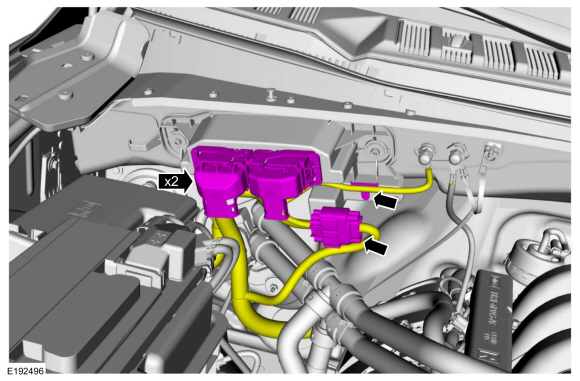
Disconnect the PCM electrical connectors, release the harness retainers to position aside wire harness.
 |
-
-
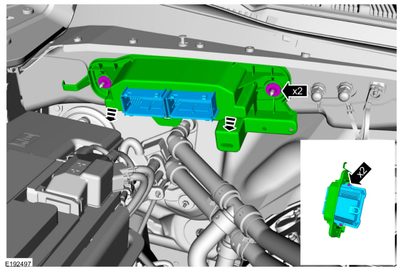
Remove the 2 retainers and the PCM .
Torque: 80 lb.in (9 Nm)
-
Remove the retainers and remove the PCM from the mounting frame.
Torque: 62 lb.in (7 Nm)
-
Remove the 2 retainers and the PCM .
 |
Installation
-
To install, reverse the removal procedure.
-
NOTE: This step is only necessary when installing a new component.
Upload the module information from the diagnostic tool using the Programmable Modules Installation routine.
Refer to: Module Programming (418-01A Module Configuration, General Procedures).
-
NOTE: This step is only necessary when installing a new component.
Carry out the Parameter Reset procedure.
Refer to: Anti-Theft Key Programming - Scan Tool (419-01B Passive Anti-Theft System (PATS), General Procedures).
-
NOTE: This step is only necessary when installing a new component.
Using the scan tool, perform the Misfire Monitor Neutral Profile Correction procedure, following the on-screen instructions.
 Oil Pressure Control Solenoid. Removal and Installation
Removal
NOTE:
Removal steps in this procedure may contain installation details.
Remove the engine front cover.
Refer to: Engine Front Cover (303-01 Engine - 3...
 Turbocharger Boost Pressure (TCBP) and Charger Air Cooler Temperature (CACT) Sensor. Removal and Installation
Removal
NOTE:
Removal steps in this procedure may contain installation details.
NOTE:
Lubricate the O ring with clean engine oil...
Other information:
Lincoln Navigator 2018-2025 Workshop Manual: Specifications
Coolant Capacity: Vehicles Built Up To: 08-July-2018 Name Fill Capacity Material: Motorcraft® Orange Concentrated Antifreeze/Coolant / VC-3-B (WSS-M97B44-D) Base radiator — 18...
Lincoln Navigator 2018-2025 Workshop Manual: Light Sensor. Removal and Installation
Special Tool(s) / General Equipment Interior Trim Remover Removal Using a non-marring tool release and position the light sensor. Use the General Equipment: Interior Trim Remover Disconnect the light sensor electrical connector and remove the light sensor...
Categories
- Manuals Home
- 4th Gen Lincoln Navigator Service Manual (2018 - 2025)
- Vehicle Dynamics Control Module (VDM). Removal and Installation
- Front Bumper Cover. Removal and Installation
- Brake Service Mode Activation and Deactivation. General Procedures
- Service Information
- Power Running Board (PRB). Diagnosis and Testing
Axle Tube Bearing. Removal and Installation
Special Tool(s) / General Equipment
 205-123
(T78P-1177-A)
205-123
(T78P-1177-A)
Installer, Axle Shaft Oil Seal
 308-047
(T77F-1102-A)
308-047
(T77F-1102-A)
Remover, Bearing Cup Slide Hammer