Lincoln Navigator: Rear Climate Control / Rear Climate Control Housing. Removal and Installation
Removal
NOTICE: During the removal or installation of components, cap, tape or otherwise appropriately protect all openings and tubes/fittings to prevent the ingress of dirt or other contamination. Remove caps, tape and other protective materials prior to installation.
NOTE: Removal steps in this procedure may contain installation details.
-
Recover the refrigerant. Refer to the appropriate Recovery procedure in Group 412.
-
Drain the cooling system.
Refer to: Cooling System Draining, Vacuum Filling and Bleeding (303-03 Engine Cooling - 3.5L EcoBoost (272kW/370PS)) .
-
Remove the RH loadspace trim panel.
Refer to: Loadspace Trim Panel (501-05 Interior Trim and Ornamentation, Removal and Installation).
-
NOTE: Be prepared to collect escaping fluid.
Disconnect the quick release couplings from the rear heater core.
Refer to: Quick Release Coupling (310-00 Fuel System - General Information - 3.5L EcoBoost (272kW/370PS)) .
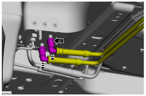 |
-
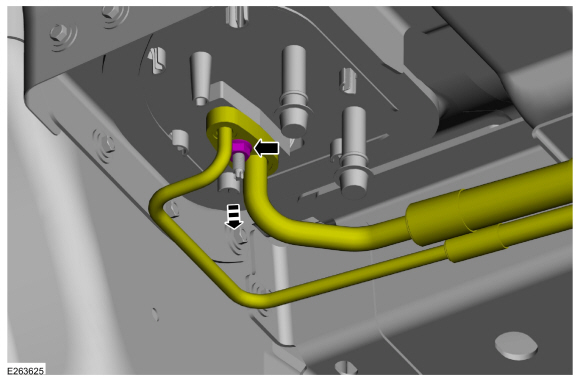
Remove the nut and position the rear thermostatic expansion valve manifold and tube assembly aside.
-
Make sure to cover any open ports to prevent debris from entering the system.
Torque: 80 lb.in (9 Nm)
-
Make sure to cover any open ports to prevent debris from entering the system.
 |
-
-
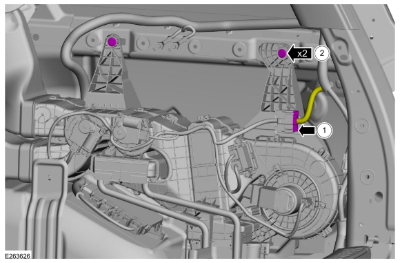
Disconnect the electrical connector.
-
Remove the bolts.
Torque: 71 lb.in (8 Nm)
-
Disconnect the electrical connector.
 |
-
Disconnect the electrical connector and remove the rear footwell duct.
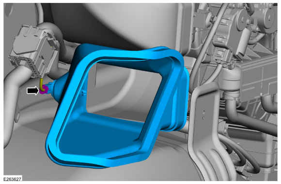 |
-
-
Disconnect the duct.
-
Remove the rear climate control housing.
-
Disconnect the duct.
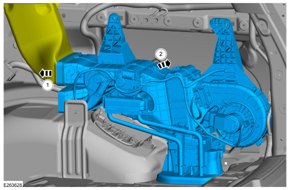 |
Installation
-
To install, reverse the removal procedure.
-
NOTICE: Only use the specified material to lubricate the seals.
Install and lubricate new O-ring seals. Refer to the appropriate Specifications in Group 412.
-
Lubricate the refrigerant system with the correct amount
of clean PAG oil. Refer to the appropriate Refrigerant Oil Adding
procedure in Group 412.
-
Fill and bleed the cooling system.
Refer to: Cooling System Draining, Vacuum Filling and Bleeding (303-03 Engine Cooling - 3.5L EcoBoost (272kW/370PS)) .
 Rear Blower Motor Speed Control. Removal and Installation
Removal
NOTE:
Removal steps in this procedure may contain installation details.
Remove the RH loadspace trim panel.
Refer to: Loadspace Trim Panel (501-05 Interior Trim and Ornamentation, Removal and Installation)...
 Rear Evaporator. Removal and Installation
Removal
NOTICE:
During the removal or installation of components, cap, tape
or otherwise appropriately protect all openings and tubes/fittings to
prevent the ingress of dirt or other contamination...
Other information:
Lincoln Navigator 2018-2025 Workshop Manual: Auxiliary Power Point. Removal and Installation
Special Tool(s) / General Equipment 501-194Remover, Power PointTKIT-2014D-ROW2TKIT-2014D-FL_ROW Removal Open the power point cover. Position the power point extractor so that it engages in the adjacent slots in the power point socket...
Lincoln Navigator 2018-2025 Workshop Manual: Information and Entertainment System. Diagnosis and Testing
Diagnostic Trouble Code (DTC) Chart Diagnostics in this manual assume a certain skill level and knowledge of Ford-specific diagnostic practices. REFER to: Diagnostic Methods (100-00 General Information, Description and Operation). Module DTC Description Action ACM B116A:01 Handset Microphone: General Electrical Failure GO to Pinpoint Test V ACM B116A:12 ..
Categories
- Manuals Home
- 4th Gen Lincoln Navigator Service Manual (2018 - 2025)
- Liftgate Trim Panel. Removal and Installation
- Head Up Display (HUD) Module Calibration. General Procedures
- Remote Function Actuator (RFA) Module. Removal and Installation
- Satellite Radio Antenna. Removal and Installation
- Rear View Mirrors - System Operation and Component Description. Description and Operation
Rear Camber Adjustment. General Procedures
Special Tool(s) / General Equipment
Wheel Alignment SystemActivation
NOTICE: Suspension fasteners are critical parts that affect the performance of vital components and systems. Failure of these fasteners may result in major service expense. Use the same or equivalent parts if replacement is necessary. Do not use a replacement part of lesser quality or substitute design. Tighten fasteners as specified.
Using alignment equipment and the manufacturer's instructions, measure the rear camber.Use the General Equipment: Wheel Alignment System