Lincoln Navigator: Climate Control System - General Information / Climate Control System - Component Location. Description and Operation

| Item | Description |
|---|---|
| 1 | Driver Side Register |
| 2 | In-Vehicle Temperature & Humidity Sensor |
| 3 | Auto Lamp & Sunload Sensor |
| 4 | Passenger Side Register |
| 5 | Center Registers |
| 6 | FCIM & HVAC Module |
| Item | Description |
|---|---|
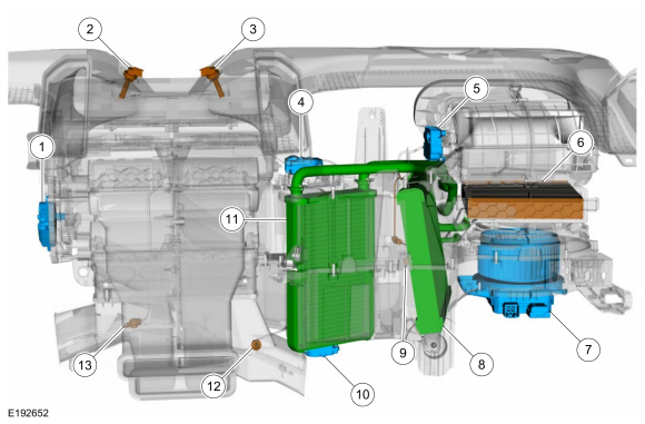
| 1 | Air Distribution Door Actuator |
| 2 | Driver Side Register Air Discharge Temperature Sensor |
| 3 | Passenger Side Register Air Discharge Temperature Sensor |
| 4 | Passenger Side Temperature Door Actuator |
| 5 | Air Inlet Door Actuator |
| 6 | Cabin Air Filter |
| 7 | Blower Motor Control Module |
| 8 | Evaporator |
| 9 | Evaporator Temperature Sensor |
| 10 | Temperature Door Actuator |
| 11 | Heater Core |
| 12 | Passenger Side Footwell Air Discharge Temperature Sensor |
| 13 | Driver Side Footwell Air Discharge Temperature Sensor |
| Item | Description |
|---|---|
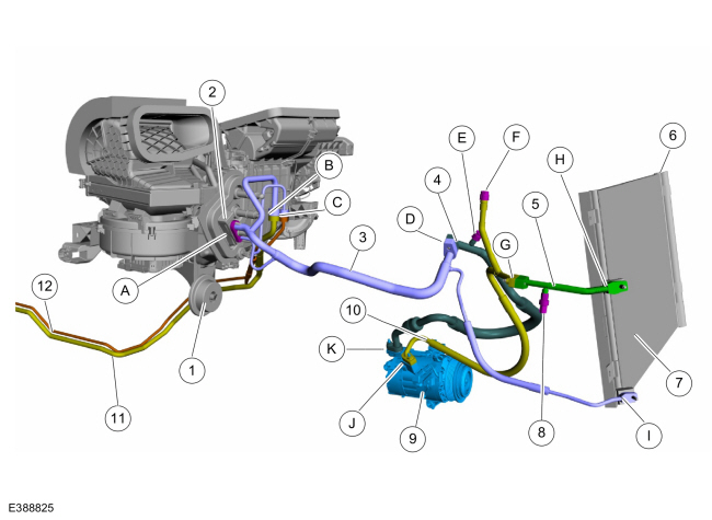
| 1 | Condensation drain |
| 2 | Thermostatic expansion valve |
| 3 | Thermostatic expansion valve manifold and tube assembly |
| 4 | A/C compressor inlet line |
| 5 | A/C condenser to A/C compressor outlet line |
| 6 | Desiccant bag |
| 7 | Condenser |
| 8 | A/C pressure transducer |
| 9 | A/C compressor |
| 10 | A/C condenser outlet line |
| 11 | Rear evaporator outlet line |
| 12 | Rear evaporator inlet line |
| A | Thermostatic expansion valve fitting |
| B | Rear evaporator outlet line fitting |
| C | Rear evaporator inlet line fitting |
| D | A/C compressor inlet line to A/C thermostatic expansion valve manifold and tube assembly fitting |
| E | Low side service port |
| F | High side service port |
| G | Condenser to A/C compressor outlet line fitting |
| H | Condenser inlet fitting |
| I | Condenser outlet fitting |
| J | Compressor outlet fitting |
| K | Compressor inlet fitting |

| Item | Description |
|---|---|
| 1 | Condenser |
| 2 | A/C Pressure Transducer |
| 3 | A/C Compressor Outlet Line |
| 4 | A/C Compressor Inlet Line |
| 5 | A/C Compressor |
| 6 | Thermostatic Expansion Valve Manifold and Tube Assembly |
| 7 | Thermostatic Expansion Valve |
| 8 | Climate Control Housing |
| 9 | If equipped, Ambient Air Quality Sensor |
| 10 | Desiccant Bag |
| 11 | Ambient Air Temperature Sensor |

 Climate Control System - System Operation and Component Description. Description and Operation
System Operation
System Diagram
E371291
*.sttxt {
visibility: hidden;
}
*.stcallout {
visibility: visible;
}
1
GWM
2
Cabin heater
coolant pump
3
Externally Controlled
Variable Dsiplacement
Compressor (EVDC)
..
Other information:
Lincoln Navigator 2018-2025 Workshop Manual: Module Controlled Functions - Component Location. Description and Operation
Item Description 1 BCMC 2 BCM 3 PDM 4 RTM 5 DDM ..
Lincoln Navigator 2018-2025 Workshop Manual: Front Active Park Assist Sensors. Removal and Installation
Removal NOTE: Removal steps in this procedure may contain installation details. NOTE: LH side shown, RH side similar. Remove the front wheel and tire assembly. Refer to: Wheel and Tire (204-04A Wheels and Tires, Removal and Installation). Remove the front fender liner screws. Torque: 15 lb.in (1.7 Nm) ..
Categories
- Manuals Home
- 4th Gen Lincoln Navigator Service Manual (2018 - 2025)
- Body Control Module (BCM). Removal and Installation
- Head Up Display (HUD) Module Calibration. General Procedures
- Body and Paint
- Power Running Board (PRB). Diagnosis and Testing
- Transmission Fluid Level Check. General Procedures
Differential Case Runout Check. General Procedures
Special Tool(s) / General Equipment
 205-1016
Installer, Differential Bearing
TKIT-2014D-ROW2
TKIT-2014D-FL_ROW
 205-153
(T80T-4000-W)
205-153
(T80T-4000-W)
Handle
 205-D061
(D83T-4205-C2)
205-D061
(D83T-4205-C2)
Step Plate Dial Indicator Three Leg Puller Punch