Lincoln Navigator: Automatic Transmission - 10-Speed Automatic Transmission – 10R80 / Main Control Valve Body. Description and Operation
| Item | Description |
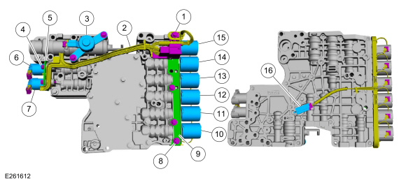
| 1 | Internal wiring harness retaining bolt |
| 2 | Internal wiring harness |
| 3 | Park lock pawl solenoid |
| 4 | Solenoid retaining plate bolts |
| 5 | Solenoid retaining plate |
| 6 | TCC solenoid |
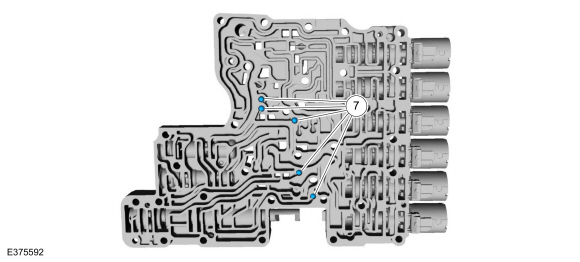
| 7 | LPC solenoid |
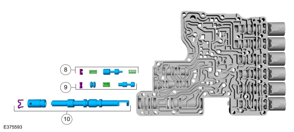
| 8 | Shift solenoid retaining plate bolts |
| 9 | Shift solenoid retaining plate |
| 10 | SSD |
| 11 | SSE |
| 12 | SSB |
| 13 | SSC |
| 14 | SSF |
| 15 | SSA |
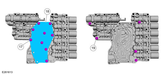
| 16 | TFT |
| 17 | Valve channel plate bolts |
| 18 | Valve channel plate |
| 19 | Lower-to-upper valve body bolts |
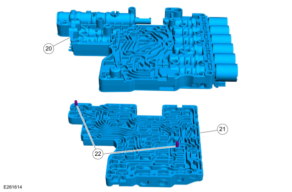
| 20 | Lower valve body |
| 21 | Upper valve body |
| 22 | Valve body dowel pins |
Lower Valve Body
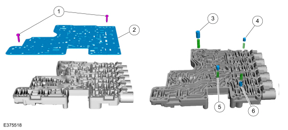
| 1 | Valve body separator plate bolts |
| 2 | Valve body separator plate |
| 3 | LPC damper assembly |
| 4 | Clutch exhaust check valve |
| 5 | Torque converter anti-drainback valve |
| 6 | Transmission fluid auxiliary pump check valve |
| 7 | Check balls (quantity 5) |
| 8 | LPC anti-backflow valve assembly |
| 9 | TCC priority valve assembly |
| 10 | Park lock pawl valve |
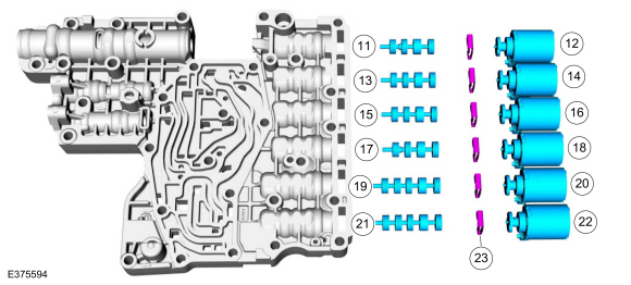
| 11 | A clutch control valve |
| 12 | SSA |
| 13 | F clutch control valve |
| 14 | SSF |
| 15 | C clutch control valve |
| 16 | SSC |
| 17 | B clutch control valve |
| 18 | SSB |
| 19 | E clutch control valve |
| 20 | SSE |
| 21 | D clutch control valve |
| 22 | SSD |
| 23 | Shift solenoid retainers |
Upper Valve Body
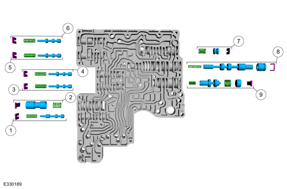
| 1 | Lube control valve assembly |
| 2 | Plug and spring assembly |
| 3 | C clutch latch valve assembly |
| 4 | B clutch latch valve assembly |
| 5 | F clutch latch valve assembly |
| 6 | A clutch latch valve assembly |
| 7 | Plug and spring assembly |
| 8 | TCC regulator valve assembly |
| 9 | Main regulator valve assembly |
The main control consists of a upper and lower valve body with solenoids that are controlled by a remote mounted TCM or the PCM . The TCM or PCM operates the electrical components to provide refined engagement feel, shift feel, and shift scheduling.
Clutch Control Valves
The A, B, C, and F clutch control valves regulate line pressure for smooth clutch application. The clutch control valve design includes a slightly smaller land at the right end of the valve. The adjacent different diameter lands creates a differential chamber. Fluid under pressure in this chamber applies more force to the larger diameter land than to the smaller diameter land.
- The clutch control valve moves to open or close a passage between line pressure and the clutch control circuit. With the valve at the left of the bore, the passage between line pressure and X clutch control is restricted (closed) and the clutch is released. With the valve at the right of the bore, the passage between line pressure and X clutch control is not restricted (open) and the clutch is applied.
- The clutch control valve is positioned in the bore by balancing two opposing forces. On the left side of the valve is the shift solenoid that pushes the valve to the right, thereby opening the passage and increasing pressure in the clutch control circuit.
- Clutch control pressure in the differential chamber applies more force to the land on the left pushing the valve towards the solenoid, thereby lowering pressure in the clutch control circuit.
- When the shift solenoid is de-energized, the weight of the fluid in the elevated exhaust circuit acts on the clutch control valve to keep it positioned against the solenoid pintle. The passage from line pressure to X clutch control is closed.
- To apply the clutch, the TCM or PCM applies current to the shift solenoid and hydraulic pressure in the X clutch control circuit increases proportionally.
- As the solenoid force increases, the clutch control valve moves and connects line pressure to X clutch control.
- X clutch control fluid begins to fill the clutch. X clutch control also acts on the clutch control valve via the differential chamber.
- The clutch control valve cycles rapidly as the X clutch control pressure increases and the clutch applies.
The D and E clutch control valves regulate line pressure for smooth clutch application. The clutch control valve design is similar to the A, B, C, and F clutch control valves, except there are 2 progressively smaller diameter lands at the right end of the valve. The different diameter lands create two differential chambers. Valve operation is identical to the other clutch control valves except the D and E clutch control valves can use 2 different forces to balance the valve against the solenoid. Under low load conditions, the X clutch control circuit feeds both differential chambers resulting more force acting against the solenoid. The clutch control valve is positioned close to the solenoid and about 689 kPa (100 psi) of regulated line pressure applies or holds the clutch. Under high load conditions, the X clutch control circuit feeds only 1 differential chamber resulting in less force acting against the solenoid. The clutch control valve is positioned further away from the solenoid and about 1,379 kPa (200 psi) of regulated line pressure applies or holds the clutch.

 Pump Assembly. Description and Operation
Overview
Item
Description
1
Transmission fluid pump drive gear
2
Transmission fluid pump idler gear
3
Transmission fluid pump assembly
4
Transmission fluid filter
The
transmission fluid in the sump area at the bottom of the transm..
Other information:
Lincoln Navigator 2018-2025 Workshop Manual: Differential Carrier - Vehicles With: Electronic Limited-Slip Differential. Removal and Installation
Special Tool(s) / General Equipment 205-220Installer, Differential ShimTKIT-1985-FH 307-003 (T57L-500-B) Holding Fixture, Transmission Copper Hammer Removal Remove the HCU from the rear axle assembly. Refer to: Hydraulic Control Unit (HCU) (205-02 Rear Drive Axle/Differential - Vehicles With: Ford 9.75 Inch Ring Gear, Removal and ..
Lincoln Navigator 2018-2025 Workshop Manual: Trailer Hitch. Removal and Installation
Removal NOTE: Removal steps in this procedure may contain installation details. Remove the rear bumper cover. Refer to: Rear Bumper Cover (501-19 Bumpers, Removal and Installation). Disconnect the electrical connector, disengage the retainers from trailer hitch and position aside the wiring harness. ..
Categories
- Manuals Home
- 4th Gen Lincoln Navigator Service Manual (2018 - 2025)
- Vehicle Dynamics Control Module (VDM). Removal and Installation
- Remote Function Actuator (RFA) Module. Removal and Installation
- Front Bumper. Removal and Installation
- Rear View Mirrors - System Operation and Component Description. Description and Operation
- Liftgate Trim Panel. Removal and Installation
Rear Camber Adjustment. General Procedures
Special Tool(s) / General Equipment
Wheel Alignment SystemActivation
NOTICE: Suspension fasteners are critical parts that affect the performance of vital components and systems. Failure of these fasteners may result in major service expense. Use the same or equivalent parts if replacement is necessary. Do not use a replacement part of lesser quality or substitute design. Tighten fasteners as specified.
Using alignment equipment and the manufacturer's instructions, measure the rear camber.Use the General Equipment: Wheel Alignment System