Lincoln Navigator: Roof Sheet Metal Repairs / Roof Side Rail Section. Removal and Installation
Special Tool(s) /
General Equipment
| 6.5 mm Drill Bit |
| Polydrive Bit Socket |
| Self-Piercing Rivet (SPR) Remover/Installer |
| Belt Sander |
| Blind Rivet Gun |
| Air Body Saw |
| MIG/MAG Welding Equipment |
| Locking Pliers |
Materials
| Name |
Specification |
Metal Bonding Adhesive
TA-1, TA-1-B, 3M™ 08115, LORD Fusor® 108B, Henkel Teroson EP 5055 |
-
|
Seam Sealer
TA-2-B, 3M™ 08308, LORD Fusor® 803DTM |
-
|
Flexible Foam Repair
3M™ 08463, LORD Fusor® 121 |
-
|
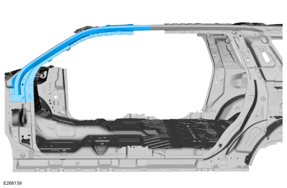
Removal
NOTE:
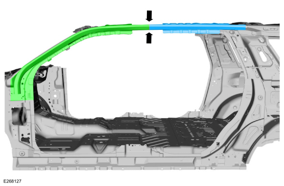
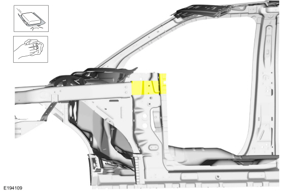
The roof side rail may be sectioned as a front or rear half .
Depending on damage type, follow the appropriate steps below.
NOTE:
LH side shown, RH similar.
NOTE:
Aluminum body panels are highly receptive to heat transfer.
With the extensive use of structural adhesives and non-structural
sealers used in vehicle construction, the potential of heat transfer
could impact adhesives and sealers in non-associated panels during the
repair process. Many repairs areas that utilize structural adhesive may
be separated after fastener removal by using a panel chisel along the
joint/flange. Using heat not exceeding 425° F to loosen a bonded panel
should only be done when all panels in the joint will be replaced and
new adhesive applied.
-
Sectioning point: Sectioning is possible and reasonable.
All Vehicles
-
Depower the SRS .
Refer to: Supplemental Restraint System (SRS) Depowering (501-20B Supplemental Restraint System, General Procedures).
-
Make sure the vehicle is dimensionally correct.
Refer to: Body and Frame (501-26 Body Repairs - Vehicle Specific Information and Tolerance Checks, Description and Operation).
-
Remove the outer roof panel.
Refer to: Roof Panel (501-28 Roof Sheet Metal Repairs, Removal and Installation).
Refer to: Roof Panel - Vehicles With: Roof Opening Panel (501-28 Roof Sheet Metal Repairs, Removal and Installation).
Front Section
-
Remove the front fender.
Refer to: Fender (501-02 Front End Body Panels, Removal and Installation).
-
Remove the front and rear doors.
Refer to: Front Door (501-03 Body Closures, Removal and Installation).
Refer to: Rear Door (501-03 Body Closures, Removal and Installation).
-
Remove the instrument panel.
Refer to: Instrument Panel (501-12 Instrument Panel and Console, Removal and Installation).
-
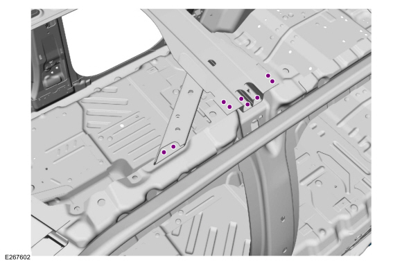
Remove the 3 bolts and the cross-car beam bracket.
-
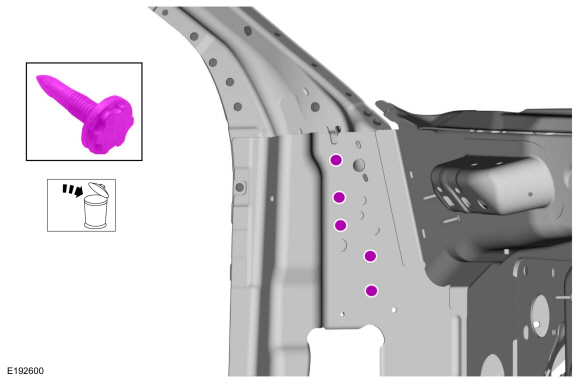
Remove and discard the FDS fasteners.
Use the General Equipment: Polydrive Bit Socket
-
Remove the A-pillar reinforcement.
Refer to: A-Pillar Outer Panel Section and Reinforcement (501-29 Side Panel Sheet Metal Repairs, Removal and Installation).
-
Remove the B-pillar reinforcement.
Refer to: B-Pillar and Reinforcement (501-29 Side Panel Sheet Metal Repairs, Removal and Installation).
-
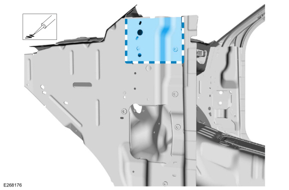
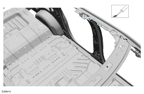
Remove the SPR fasteners from the windshield header and roof side rail gusset.
Use the General Equipment: Self-Piercing Rivet (SPR) Remover/Installer
Use the General Equipment: Belt Sander
-
NOTE:
Vehicles without roof opening panel.
Remove the SPR fasteners from the roof reinforcement assembly.
Use the General Equipment: Self-Piercing Rivet (SPR) Remover/Installer
Use the General Equipment: Belt Sander
-
Remove SPR fasteners from the upper B-pillar panel.
Use the General Equipment: Self-Piercing Rivet (SPR) Remover/Installer
Use the General Equipment: Belt Sander
-
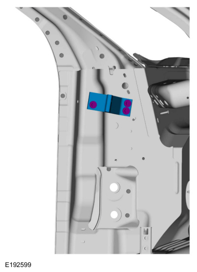
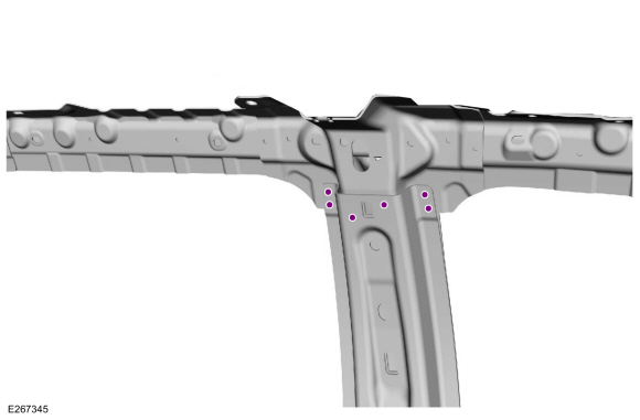
Remove the SPR fasteners, remove and discard the FDS fasteners and remove the B-pillar gusset from the roof side rail.
Use the General Equipment: Self-Piercing Rivet (SPR) Remover/Installer
Use the General Equipment: Belt Sander
Use the General Equipment: Polydrive Bit Socket
-
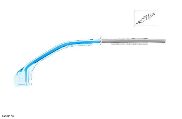
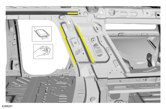
Carefully measure and cut the tube portion only.
Use the General Equipment: Air Body Saw
-
Remove the roof side rail front section.
Rear Section
-
Remove the B-pillar reinforcement.
Refer to: B-Pillar and Reinforcement (501-29 Side Panel Sheet Metal Repairs, Removal and Installation).
-
Remove the quarter panel.
-
NOTE:
Vehicles without roof opening panel.
Remove the SPR fasteners from the roof reinforcement assembly.
Use the General Equipment: Self-Piercing Rivet (SPR) Remover/Installer
Use the General Equipment: Belt Sander
-
Remove and SPR fasteners from the upper B-pillar panel.
Use the General Equipment: Self-Piercing Rivet (SPR) Remover/Installer
Use the General Equipment: Belt Sander
-
Remove the SPR fasteners, remove and discard the FDS fasteners and remove the B-pillar gusset from the roof side rail.
Use the General Equipment: Self-Piercing Rivet (SPR) Remover/Installer
Use the General Equipment: Belt Sander
Use the General Equipment: Polydrive Bit Socket
-
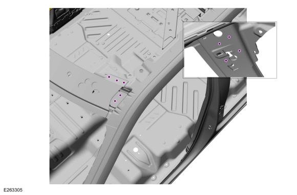
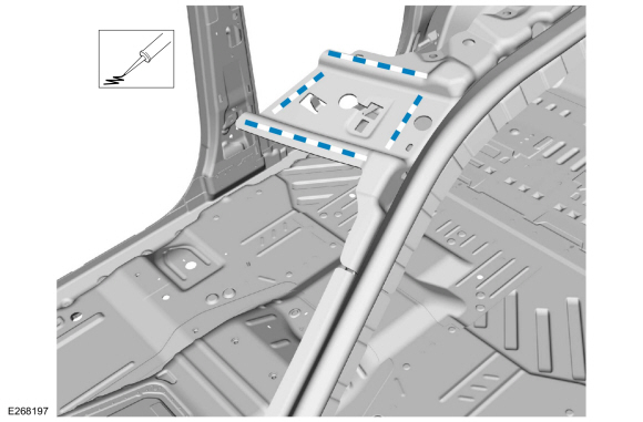
Remove and discard the FDS fasteners and SPR fasteners from the quarter panel upper reinforcement.
Use the General Equipment: Polydrive Bit Socket
Use the General Equipment: Self-Piercing Rivet (SPR) Remover/Installer
Use the General Equipment: Belt Sander
-
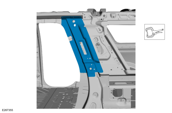
Remove the quarter panel upper reinforcement.
-
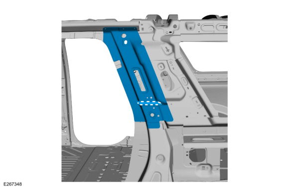
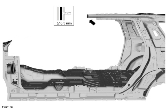
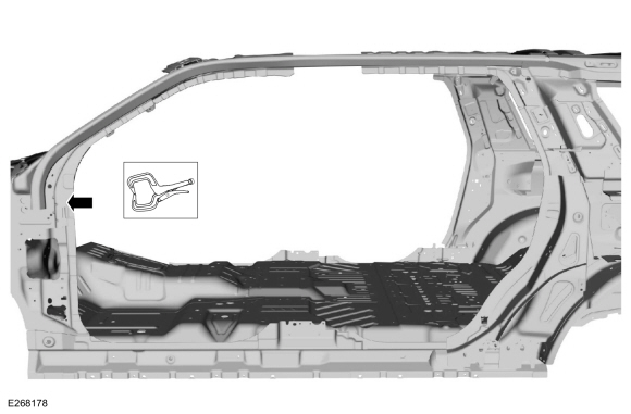
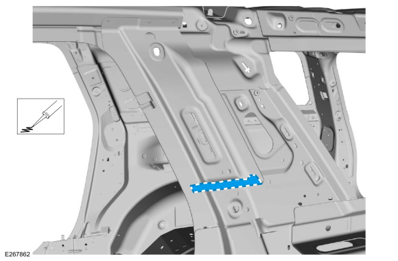
NOTE:
Locate cutline at center of the b-pillar gusset.
Carefully cut and remove the roof side rail section as indicated.
Use the General Equipment: Air Body Saw
Installation
NOTE:
SPR fasteners may not be placed directly over original SPR location.
They must be placed adjacent to original location matching original
quantity.
NOTE:
Solid rivets or blind rivet fasteners may be used in place of SPR
fasteners in original SPR position after enlarging hole to 6.5mm
All Vehicles
-
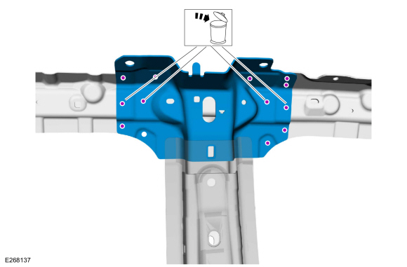
Remove the SPR fasteners, remove and discard the FDS fasteners and the
B-pillar gusset from the roof side rail service replacement part.
Use the General Equipment: Self-Piercing Rivet (SPR) Remover/Installer
Use the General Equipment: Belt Sander
Use the General Equipment: Polydrive Bit Socket
Front Section
-
Sand to remove old adhesive using 80 grit sand paper and clean as indicated.
-
Cut the roof side rail tube service part as indicated.
Use the General Equipment: Air Body Saw
-
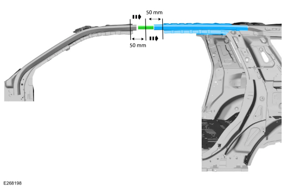
Create a 100 mm insert from an unused portion of the old component or the service part.
Refer to: Joining Techniques (501-25 Body Repairs - General Information, General Procedures).
-
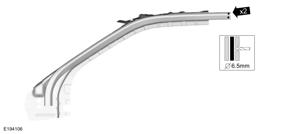
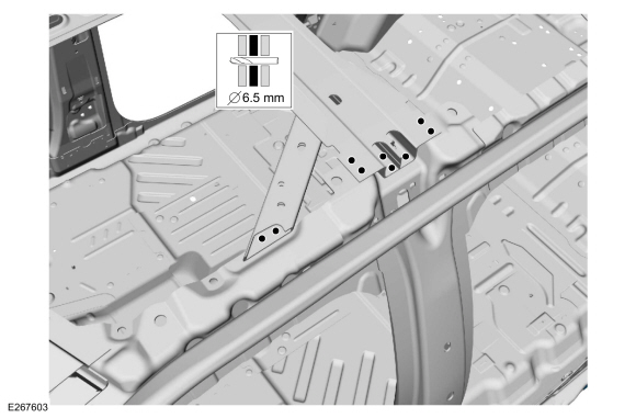
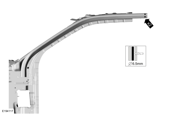
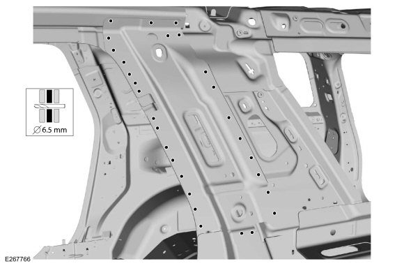
Drill two 6.5mm plug weld holes in existing frame rail as indicated.
Use the General Equipment: 6.5 mm Drill Bit
-
Drill two 6.5mm plug weld holes in replacement rail as indicated.
Use the General Equipment: 6.5 mm Drill Bit
-
Apply adhesive to the A-pillar mating surface.
Material: Metal Bonding Adhesive
/ TA-1, TA-1-B, 3M™ 08115, LORD Fusor® 108B, Henkel Teroson EP 5055
-
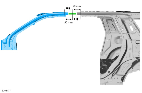
NOTE:
100mm insert should extend 50mm in to service part section and original component.
Install insert and service replacement section as indicated.
-
Clamp front rail replacement section in position.
Use the General Equipment: Locking Pliers
-
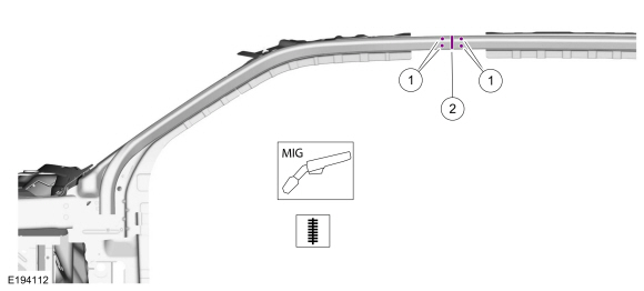
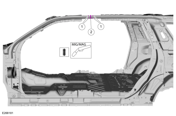
Weld as indicated.
-
Install MIG plug welds.
Use the General Equipment: MIG/MAG Welding Equipment
-
Entirely seam weld as indicated.
Use the General Equipment: MIG/MAG Welding Equipment
-
Apply NVH foam along the roof rail as noted during removal.
Material: Flexible Foam Repair
/ 3M™ 08463, LORD Fusor® 121
-
Metal finish as required.
-
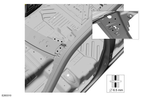
Install, clamp and drill side rail to B-pillar gusset as indicated.
Use the General Equipment: Locking Pliers
Use the General Equipment: 6.5 mm Drill Bit
-
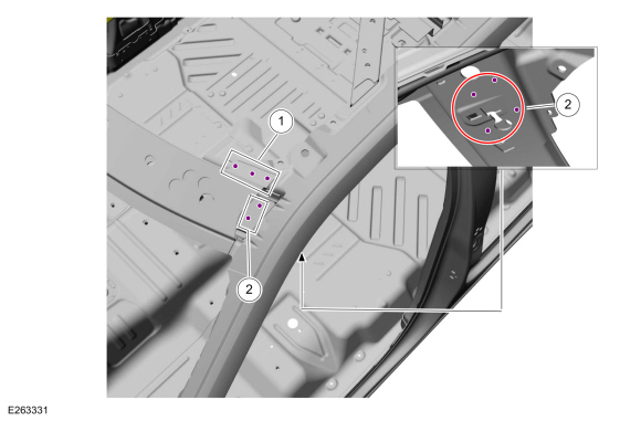
NOTE:
SPR fasteners may not be placed directly over original SPR location.
They must be placed adjacent to original location matching original
quantity.
NOTE:
Solid rivets or blind rivet fasteners may be used in place of SPR
fasteners in original SPR position after enlarging hole to 6.5mm
Install fasteners.
|
Item
|
SPR Number
|
SPR Code
|
Henrob® Mandrel
|
Pro-Spot® Mandrel
|
Blind Rivet
|
Solid Rivet
|
Rivnut®
|
|
1
|
-
|
-
|
-
|
-
|
W708777-S900C
|
|
|
Use the General Equipment: Blind Rivet Gun
-
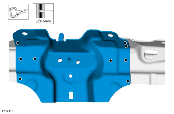
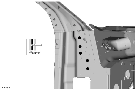
Position the B-pillar inner panel and drill 6.5mm holes as indicated.
Use the General Equipment: Locking Pliers
Use the General Equipment: 6.5 mm Drill Bit
-
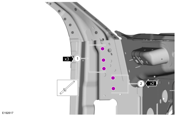
NOTE:
SPR fasteners may not be placed directly over original SPR location.
They must be placed adjacent to original location matching original
quantity.
NOTE:
Solid rivets or blind rivet fasteners may be used in place of SPR
fasteners in original SPR position after enlarging hole to 6.5mm
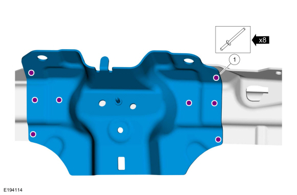
Install fasteners.
|
Item
|
SPR Number
|
SPR Code
|
Henrob® Mandrel
|
Pro-Spot® Mandrel
|
Blind Rivet
|
Solid Rivet
|
Rivnut®
|
|
1
|
W717186-S900
|
EN
|
DG11-200/H
|
SA-0400/SA-0401
|
-
|
W790376-S900
|
-
|
|
2
|
-
|
-
|
-
|
-
|
W708777-S900C
|
-
|
-
|
Refer to: Joining Techniques (501-25 Body Repairs - General Information, General Procedures).
Use the General Equipment: Self-Piercing Rivet (SPR) Remover/Installer
Use the General Equipment: Blind Rivet Gun
-
NOTE:
Vehicles without roof opening panel.
Apply adhesive to the mating surface.
Material: Metal Bonding Adhesive
/ TA-1, TA-1-B, 3M™ 08115, LORD Fusor® 108B, Henkel Teroson EP 5055
-
NOTE:
Vehicles without roof opening panel.
Position the roof reinforcement assembly, clamp and drill 6.5mm holes as indicated.
Use the General Equipment: 6.5 mm Drill Bit
-
NOTE:
Vehicles without roof opening panel.
NOTE:
SPR fasteners may not be placed directly over original SPR location.
They must be placed adjacent to original location matching original
quantity.
NOTE:
Solid rivets or blind rivet fasteners may be used in place of SPR
fasteners in original SPR position after enlarging hole to 6.5mm
Install fasteners.
|
Item
|
SPR Number
|
SPR Code
|
Henrob® Mandrel
|
Pro-Spot® Mandrel
|
Blind Rivet
|
Solid Rivet
|
Rivnut®
|
|
1
|
-
|
-
|
-
|
-
|
W708777-S900C
|
-
|
-
|
|
2
|
-
|
-
|
|
|
W707638-S900C
|
-
|
-
|
Use the General Equipment: Blind Rivet Gun
-
Apply adhesive to mating surface.
Material: Metal Bonding Adhesive
/ TA-1, TA-1-B, 3M™ 08115, LORD Fusor® 108B, Henkel Teroson EP 5055
-
Position the windshield header panel, clamp and drill 6.5mm holes as indicated.
Use the General Equipment: 6.5 mm Drill Bit
-
NOTE:
SPR fasteners may not be placed directly over original SPR location.
They must be placed adjacent to original location matching original
quantity.
NOTE:
Solid rivets or blind rivet fasteners may be used in place of SPR
fasteners in original SPR position after enlarging hole to 6.5mm
Install the fasteners.
|
Item`
|
SPR Number
|
SPR Code
|
Henrob® Mandrel
|
Pro-Spot® Mandrel
|
Blind Rivet
|
Solid Rivet
|
Rivnut®
|
|
1
|
-
|
-
|
-
|
-
|
W708777-S900C
|
-
|
-
|
|
2
|
W710246-S900
|
BN
|
DP10-200/H
|
SA-0400/SA-0402
|
-
|
W790377-S900
|
-
|
Use the General Equipment: Self-Piercing Rivet (SPR) Remover/Installer
Use the General Equipment: Blind Rivet Gun
Use the General Equipment: Blind Rivet Gun
-
Drill the five 6.5mm holes as indicated.
Use the General Equipment: 6.5 mm Drill Bit
-
NOTE:
SPR fasteners may not be placed directly over original SPR location.
They must be placed adjacent to original location matching original
quantity.
NOTE:
Solid rivets or blind rivet fasteners may be used in place of SPR
fasteners in original SPR position after enlarging hole to 6.5mm
Install the fasteners.
|
Item
|
SPR Number
|
SPR Code
|
Henrob® Mandrel
|
Pro-Spot® Mandrel
|
Blind Rivet
|
Solid Rivet
|
Rivnut®
|
|
1
|
-
|
-
|
-
|
-
|
W702512-S900C
|
-
|
-
|
|
2
|
-
|
-
|
-
|
-
|
W708777-S900C
|
-
|
-
|
Use the General Equipment: Blind Rivet Gun
-
Install the cross-car beam bracket and the bolts.
Torque:
18 lb.ft (25 Nm)
-
Install the B-pillar reinforcement.
Refer to: B-Pillar and Reinforcement (501-29 Side Panel Sheet Metal Repairs, Removal and Installation).
-
Install the A-pillar reinforcement.
Refer to: A-Pillar Outer Panel Section and Reinforcement (501-29 Side Panel Sheet Metal Repairs, Removal and Installation).
-
Install the instrument panel.
Refer to: Instrument Panel (501-12 Instrument Panel and Console, Removal and Installation).
-
Install the body side panel. Metal finish using typical metal finishing techniques.
Refer to: Body and Frame (501-26 Body Repairs - Vehicle Specific Information and Tolerance Checks, Description and Operation).
Rear Section
-
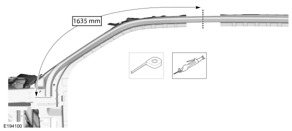
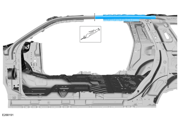
NOTE:
Measurement taken along the top of the side rail tube.
Carefully cut the tube portion only as indicated.
-
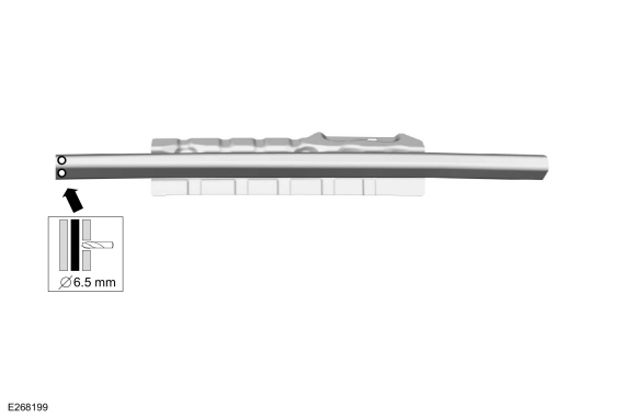
Drill two 6.5mm plug weld holes in existing frame rail as indicated.
Use the General Equipment: 6.5 mm Drill Bit
-
Drill two 6.5mm plug weld holes in the rear replacement section as indicated.
Use the General Equipment: 6.5 mm Drill Bit
-
Create a 100mm insert from an unused portion of the old component or new service part.
-
NOTE:
100mm insert should extend 50mm in to service part section and original component.
Install insert and service replacement section as indicated.
-
Weld as indicated.
-
Install MIG plug welds.
Use the General Equipment: MIG/MAG Welding Equipment
-
Entirely seam weld as indicated.
Use the General Equipment: MIG/MAG Welding Equipment
-
Sand to remove old adhesive using 80 grit sand paper and clean as indicated.
-
Apply adhesive and NVH foam (obtain locally) to the mating surface.
Material: Metal Bonding Adhesive
/ TA-1, TA-1-B, 3M™ 08115, LORD Fusor® 108B, Henkel Teroson EP 5055
Material: Flexible Foam Repair
/ 3M™ 08463, LORD Fusor® 121
-
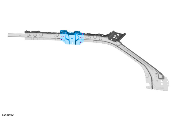
Install and clamp the C-pillar upper reinforcement in position.
Use the General Equipment: Locking Pliers
-
Drill for rivet fasteners.
Use the General Equipment: 6.5 mm Drill Bit
-
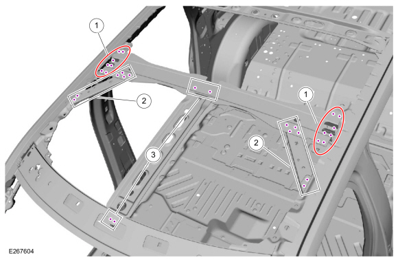
NOTE:
SPR fasteners may not be placed directly over original SPR location.
They must be placed adjacent to original location matching original
quantity.
NOTE:
Solid rivets or blind rivet fasteners may be used in place of SPR
fasteners in original SPR location after enlarging hole to 6.5mm.
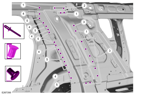
Install the fasteners as indicated.
|
Item
|
SPR Number
|
SPR Code
|
Henrob® Mandrel
|
Pro-Spot® Mandrel
|
Blind Rivet
|
Solid Rivet
|
Rivnut®
|
|
1
|
-
|
-
|
-
|
-
|
W708777-S900C
|
-
|
-
|
|
2
|
-
|
-
|
-
|
-
|
W702554-S900C
|
-
|
-
|
|
3
|
-
|
-
|
-
|
-
|
W702512-S900C
|
-
|
-
|
|
4
|
W712218-S900
|
DB
|
DP09-200H
|
SA-0400/SA-0402
|
-
|
W790377-S900
|
-
|
|
5
|
W717188-S900
|
PW
|
DG10-200H
|
SA0400/SA-0402
|
-
|
W790377-S900
|
-
|
-
Apply NVH foam as indicated.
Material: Flexible Foam Repair
/ 3M™ 08463, LORD Fusor® 121
-
Install the quater panel.
-
Install, clamp and drill roof rail to B-pillar gusset as indicated.
Use the General Equipment: Locking Pliers
Use the General Equipment: 6.5 mm Drill Bit
-
NOTE:
SPR fasteners may not be placed directly over original SPR location.
They must be placed adjacent to original location matching original
quantity.
NOTE:
Solid rivets or blind rivet fasteners may be used in place of SPR
fasteners in original SPR position after enlarging hole to 6.5mm
Install the fasteners.
|
Item
|
SPR Number
|
SPR code
|
Henrob® Mandrel
|
Pro-Spot® Mandrel
|
Blind Rivet
|
Solid Rivet
|
Rivnut®
|
|
1
|
-
|
-
|
-
|
-
|
W708777-S900C
|
-
|
-
|
Use the General Equipment: Blind Rivet Gun
-
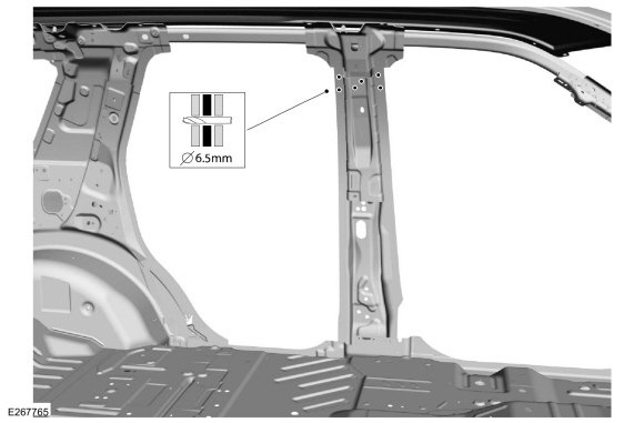
Position the B-pillar inner panel clamp and drill 6.5mm holes as indicated.
Use the General Equipment: Locking Pliers
Use the General Equipment: 6.5 mm Drill Bit
-
NOTE:
SPR fasteners may not be placed directly over original SPR location.
They must be placed adjacent to original location matching original
quantity.
NOTE:
Solid rivets or blind rivet fasteners may be used in place of SPR
fasteners in original SPR position after enlarging hole to 6.5mm
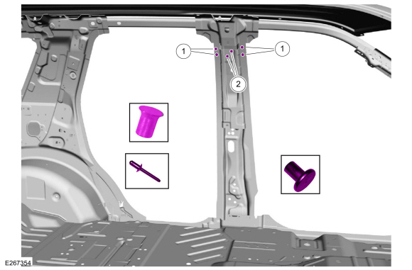
Install the fasteners.
|
Item
|
SPR Number
|
SPR Code
|
Henrob® Mandrel
|
Pro-Spot® Mandrel
|
Blind Rivet
|
Solid Rivet
|
Rivnut®
|
|
1
|
W717186-S900
|
EN
|
DG11-200/H
|
SA-0400/SA-0401
|
-
|
W790376-S900
|
-
|
|
2
|
-
|
-
|
-
|
-
|
W708777-S900C
|
-
|
-
|
Use the General Equipment: Self-Piercing Rivet (SPR) Remover/Installer
Use the General Equipment: Blind Rivet Gun
-
NOTE:
Vehicles without roof opening panel.
Apply adhesive to the mating surfaces.
-
NOTE:
Vehicles without roof opening panel.
Position the roof reinforcement assembly, clamp and drill 6.5mm holes as indicated.
Use the General Equipment: Locking Pliers
Use the General Equipment: 6.5 mm Drill Bit
-
NOTE:
Vehicles without roof opening panel.
NOTE:
SPR fasteners may not be placed directly over original SPR location.
They must be placed adjacent to original location matching original
quantity.
NOTE:
Solid rivets or blind rivet fasteners may be used in place of SPR
fasteners in original SPR position after enlarging hole to 6.5mm
Install the fasteners.
|
Item
|
SPR Number
|
SPR Code
|
Henrob® Mandrel
|
Pro-Spot® Mandrel
|
Blind Rivet
|
Solid Rivet
|
Rivnut®
|
|
1
|
-
|
-
|
-
|
-
|
W708777-S900C
|
-
|
-
|
Use the General Equipment: Blind Rivet Gun
-
Install the body side panel. Metal finish using typical metal finishing techniques.
Refer to: Body and Frame (501-26 Body Repairs - Vehicle Specific Information and Tolerance Checks, Description and Operation).
All Vehicles
-
Install the roof panel.
Refer to: Roof Panel (501-28 Roof Sheet Metal Repairs, Removal and Installation).
Refer to: Roof Panel - Vehicles With: Roof Opening Panel (501-28 Roof Sheet Metal Repairs, Removal and Installation).
-
Sand and prime the entire repair area using a Ford approved paint system.
-
Seam Sealing: All seams must be sealed to production level.
Material: Seam Sealer
/ TA-2-B, 3M™ 08308, LORD Fusor® 803DTM
-
Refinish the entire repair area using a Ford approved paint system.
-
Install the front and rear doors.
Refer to: Front Door (501-03 Body Closures, Removal and Installation).
Refer to: Rear Door (501-03 Body Closures, Removal and Installation).
-
Install the front fender.
Refer to: Fender (501-02 Front End Body Panels, Removal and Installation).
-
Align the doors as required.
Refer to: Front Door Alignment (501-03 Body Closures, General Procedures).
Refer to: Rear Door Alignment (501-03 Body Closures, General Procedures).
-
Repower the SRS .
Refer to: Supplemental Restraint System (SRS) Repowering (501-20B Supplemental Restraint System, General Procedures).
Other information:
Special Tool(s) /
General Equipment
303-1655Tool, Camshaft Holding
Removal
NOTICE:
During engine repair procedures, cleanliness is extremely
important. Any foreign material, including any material created while
cleaning gasket surfaces, that enters the oil passages, coolant passages
or the oil pan may cause engine failure.
RH and LH timing chains
..
Special Tool(s) /
General Equipment
Wooden Block
DISASSEMBLY
NOTICE:
Failure to follow the instructions below may result in damage to the TPMS .
NOTICE:
The TPMS
sensor is mounted to the valve stem. Removal of the valve stem
requires dismounting the tire from the wheel and removal of the TPMS sensor.
NOTE:
Use only the Digital Tire Pressure Gauge any tim..