Lincoln Navigator: Accessory Charging / Wireless Accessory Charging Module (WACM). Removal and Installation
Special Tool(s) / General Equipment
| Interior Trim Remover |
Removal
-
NOTE: If installing a new module, it is necessary to upload the module configuration information to the scan tool prior to removing the module. This information must be downloaded into the new module after installation.
Using a diagnostic scan tool, begin the PMI process for the WACM following the on-screen instructions.
-
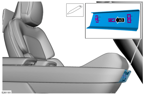
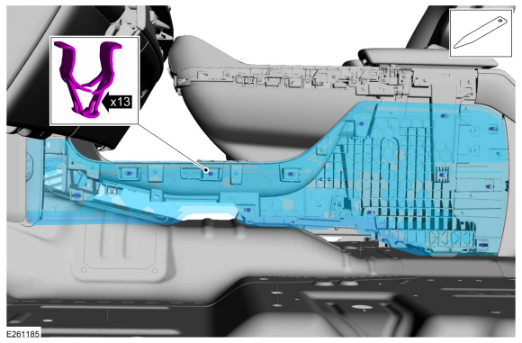
Release the clips and remove the front floor console trim panel.
Use the General Equipment: Interior Trim Remover
 |
-
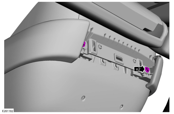
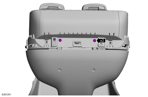
Remove the bolts.
 |
-
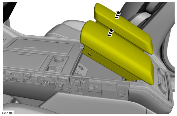
Position the floor console armrest upward.
 |
-
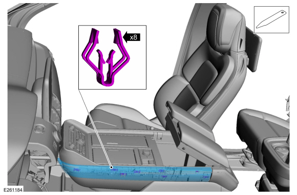
NOTE: On both sides.
Release the clips and remvoe the floor console finish panel.
Use the General Equipment: Interior Trim Remover
 |
-
NOTE: On both sides.
Release the clips and remove the floor console side trim panel.
Use the General Equipment: Interior Trim Remover
 |
-
Remove the front upper console trim panel screws.
 |
-
Remove the upper console trim panel.
-
NOTE: On both sides.
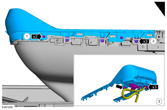
Remove the screws
-
NOTE: On both sides.
Release the clips.
-
Disconnect the electrical connectors and separate the wire harenss guide.
-
 |
-
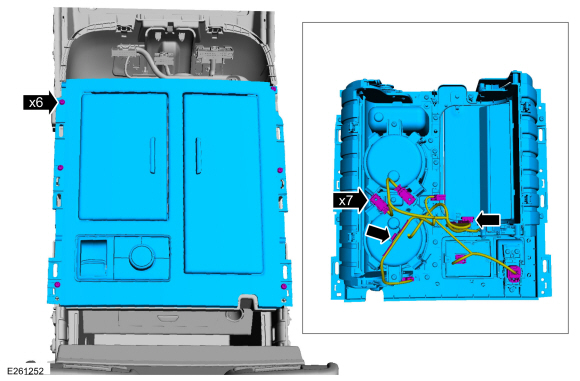
Remove the screws, disconnect the electrical connectors,
separate the wire harness guides and remove the console top plate.
 |
-
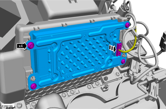
Remove the WACM .
-
Disconnect the electrical connector.
-
Disconnect the electrical connector.
 |
Installation
-
To install, reverse the removal procedure.
-
NOTE: This step is only necessary if replacing the WACM .This step is only necessary if replacing the WACM .
Using a diagnostic scan tool, complete the PMI process for the WACM following the on-screen instructions.
 Wireless Accessory Charging Module (WACM). Diagnosis and Testing
Diagnostic Trouble Code (DTC) Chart
Diagnostics in this manual assume a certain skill level and knowledge of Ford-specific diagnostic practices. REFER to: Diagnostic Methods (100-00 General Information, Description and Operation)...

Other information:
Lincoln Navigator 2018-2026 Workshop Manual: Axle Tube Bearing. Removal and Installation
Special Tool(s) / General Equipment 205-123 (T78P-1177-A) Installer, Axle Shaft Oil Seal 308-047 (T77F-1102-A) Remover, Bearing Cup Slide Hammer Removal Remove the axle shaft seal. Refer to: Axle Shaft Seal (205-03 Front Drive Axle/Differential, Removal and Installation). NOTE: Right side shown, left side sim..
Lincoln Navigator 2018-2026 Workshop Manual: Second Row Seat Head Restraint Guide Sleeve. Removal and Installation
Special Tool(s) / General Equipment Flat Headed Screw Driver Removal NOTE: Typical head restraint guide sleeve shown, others similar. Depress the tabs and remove the head restraint. NOTE: Follow the unique instructions or graphic for this step in the installation. Remove the head restraint guide sl..
Categories
- Manuals Home
- 4th Gen Lincoln Navigator Service Manual (2018 - 2026)
- Rear Bumper. Removal and Installation
- Power Running Board (PRB). Diagnosis and Testing
- Identification Codes. Description and Operation
- Remote Function Actuator (RFA) Module. Removal and Installation
- Rear View Mirrors - System Operation and Component Description. Description and Operation
Front Driveshaft. Removal and Installation
Special Tool(s) / General Equipment
Crimping ToolMaterials
Name Specification Motorcraft® Premium Long-Life GreaseXG-1-E1 ESA-M1C75-B
Removal
With the vehicle in NEUTRAL, position the vehicle on a hoist.Refer to: Jacking and Lifting (100-02 Jacking and Lifting, Description and Operation).
Remove the bolts and the transmission shield.