Lincoln Navigator: Full Frame and Body Mounting / Front Bumper Bracket. Removal and Installation
Special Tool(s) / General Equipment
| Grinder | |
| MIG/MAG Welding Equipment | |
| Locking Pliers |
Removal
 WARNING:
Frame rail crush zones absorb crash energy during a
collision and must be replaced if damaged. Prior to replacement of frame
rail crush zones, straighten damaged frame rails to correct frame
dimensions. Failure to follow these instructions may adversely affect
frame rail crush zone performance and may result in serious personal
injury to vehicle occupants in a crash.
WARNING:
Frame rail crush zones absorb crash energy during a
collision and must be replaced if damaged. Prior to replacement of frame
rail crush zones, straighten damaged frame rails to correct frame
dimensions. Failure to follow these instructions may adversely affect
frame rail crush zone performance and may result in serious personal
injury to vehicle occupants in a crash.
NOTICE: Collision damage repair must conform to the instructions contained in this workshop manual. Replacement components must be new, genuine Ford Motor Company parts. Recycled, salvaged, aftermarket or reconditioned parts (including body parts, wheels or safety restraint components) are not authorized by Ford.
NOTE: LH side shown, RH side similar.
-
Restore the vehicle to manufacturer's dimensions.
Refer to: Body and Frame (501-26 Body Repairs - Vehicle Specific Information and Tolerance Checks, Description and Operation).
-
Remove the following items:
-
Remove the front bumper.
Refer to: Front Bumper (501-19 Bumpers, Removal and Installation).
-
Remove the wheel and tire.
Refer to: Wheel and Tire (204-04A Wheels and Tires, Removal and Installation).
-
Unbolt the body mount bolts and raise or remove the body if required.
Refer to: Frame and Body Mounting (502-02 Full Frame and Body Mounting, Description and Operation).
-
Remove the front bumper.
- Anchor the vehicle to a frame rack following the equipment manufacturer's instructions.
-
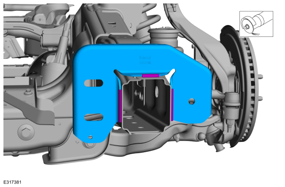
NOTE: Be careful not to cut into the frame horn, it will be reused.
NOTE: LH side shown, RH side similar
Grind the welds holding the front bumper bracket to the frame and remove the front bumper bracket.
Use the General Equipment: Grinder
 |
-
NOTE: LH side shown, RH side similar
Clean the areas of the frame where the welds were ground.
 |
Installation
-
Refer to: Joining Techniques (501-25 Body Repairs - General Information, General Procedures).
-
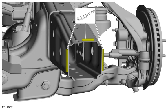
Loosely clamp the replacement bracket in a preliminary
position. Perform measurements to verify proper placement of the new
front bumper bracket, then clamp firmly into position.
-
With all measurements verified and the new front
bumper bracket in proper position, tack-weld the new front bumper
bracket in place to the frame horn.
Use the General Equipment: MIG/MAG Welding Equipment
Use the General Equipment: Locking Pliers
-
With all measurements verified and the new front
bumper bracket in proper position, tack-weld the new front bumper
bracket in place to the frame horn.
 |
-
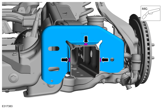
Re-check measurements, then solid weld the front bumper bracket to the frame horn.
Use the General Equipment: MIG/MAG Welding Equipment
 |
-
Metal finish the repair area using typical metal finishing techniques.
-
Restore corrosion protection.
Refer to: Corrosion Prevention (501-25 Body Repairs - General Information, General Procedures).
-
Install the wheel and tire.
Refer to: Wheel and Tire (204-04A Wheels and Tires, Removal and Installation).
-
Install the front bumper.
Refer to: Front Bumper (501-19 Bumpers, Removal and Installation).
 Frame Members-Rear Frame Section. Removal and Installation
Special Tool(s) /
General Equipment
Grinder
MIG/MAG Welding Equipment
Removal
Restore the vehicle to manufacturer's dimensions...
 Front Crossmember. Removal and Installation
Removal
WARNING:
Frame rail crush zones absorb crash energy during a
collision and must be replaced if damaged. Prior to replacement of frame
rail crush zones, straighten damaged frame rails to correct frame
dimensions...
Other information:
Lincoln Navigator 2018-2025 Workshop Manual: Image Processing Module A (IPMA). Removal and Installation
Removal If a new IPMA is being installed, using a diagnostic scan tool, begin the PMI process for the IPMA following the on-screen instructions. Disconnect the trailer tow lighting module electrical connectors. Remove the bolts and trailer tow lighting module...
Lincoln Navigator 2018-2025 Workshop Manual: Torque Converter. Description and Operation
Overview Item Description 1 TCC solenoid 2 TCC regulator valve assembly 3 TCC apply circuit 4 TCC release circuit Torque Converter Hydraulic Circuits (TCC Released) Ite..
Categories
- Manuals Home
- 4th Gen Lincoln Navigator Service Manual (2018 - 2025)
- Power Running Board (PRB). Diagnosis and Testing
- Front Bumper. Removal and Installation
- Service Information
- Liftgate Trim Panel. Removal and Installation
- Rear Bumper. Removal and Installation
Rear Camber Adjustment. General Procedures
Special Tool(s) / General Equipment
Wheel Alignment SystemActivation
NOTICE: Suspension fasteners are critical parts that affect the performance of vital components and systems. Failure of these fasteners may result in major service expense. Use the same or equivalent parts if replacement is necessary. Do not use a replacement part of lesser quality or substitute design. Tighten fasteners as specified.
Using alignment equipment and the manufacturer's instructions, measure the rear camber.Use the General Equipment: Wheel Alignment System