Lincoln Navigator: Bumpers / Front Bumper Cover. Disassembly and Assembly
Special Tool(s) /
General Equipment
DISASSEMBLY
NOTE:
Disassembly steps in this procedure may contain assembly details.
-
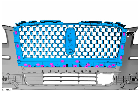
Remove the front bumper cover.
Refer to: Front Bumper Cover (501-19 Bumpers, Removal and Installation).
-
If equipped.
-
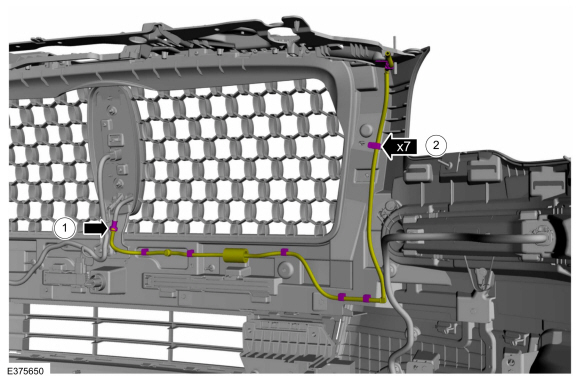
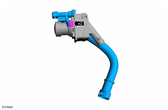
Detach the front parking aid camera washer hose coupling.
-
Separate the washer hose clips and remove the washer hose line.
-
NOTE:
The number and location of electrical connectors will vary depending on option content.
-
Disconnect the radiator grille emblem electrical connector.
-
Disconnect the front parking aid camera coaxial cable connector.
-
Disconnect the approach detection antenna electrical connector.
-
Disconnect the side repeater lamp electrical connectors.
-
Disconnect the fog lamp electrical connectors.
-
Disconnect the front parking aid sensor electrical connectors.
-
Disconnect front active park assist sensor electrical connectors.
-
NOTE:
The number and location of retainers will vary depending on option content.
Separate the harness retainers and remove the front bumper cover harness.
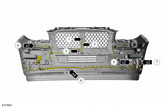
-
On both sides.
Remove the screws and the side repeater / marker lamp.
Vehicles With: Front Fog Lamps
-
On both sides.
Remove the screws and the front fog lamp assembly.
All vehicles
-
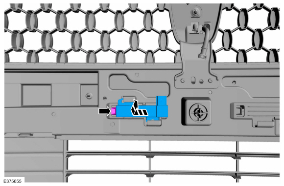
If equipped.
Release the tab and remove the approach detection antenna.
Vehicles With: Active Park Assist/Front Parking Aid
-
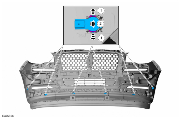
NOTE:
Make sure that the isolator rings are installed correctly while installing the sensors.
Remove the front parking aid and front active park assist sensors.
-
Release the tabs.
-
Remove the front parking aid and front active park assist sensors from the bracket.
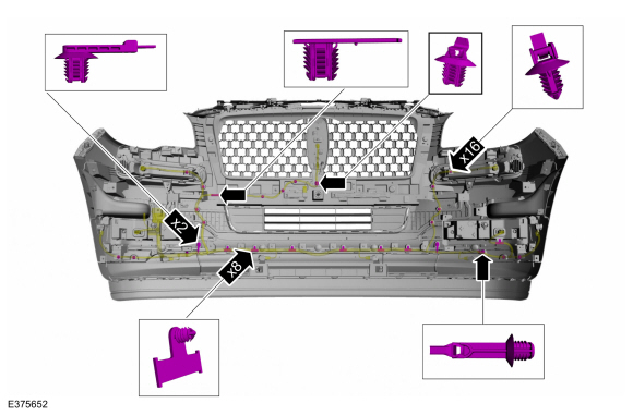
All vehicles
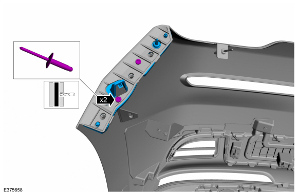
-
-
Drill the rivet.
Use the General Equipment: Electric Drill
-
Remove the screws.
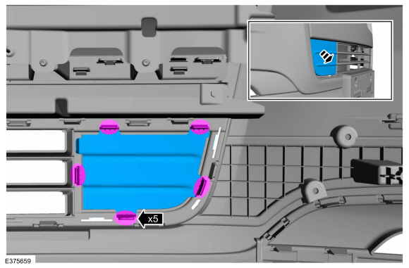
-
Release the tabs and remove the air curtain bezel.
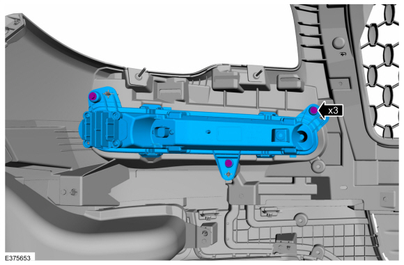
-
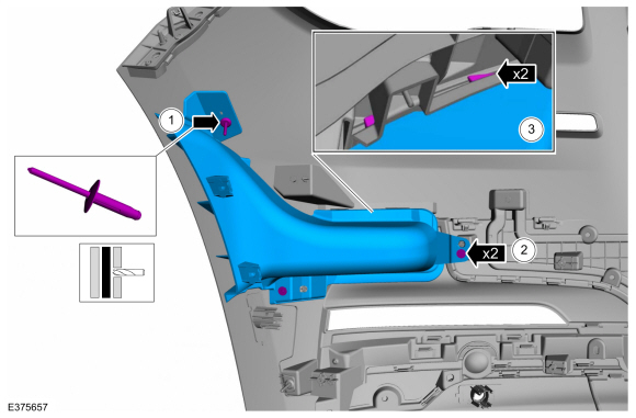
On both sides.
Drill the rivets and remove the front bumper cover to fender bracket.
Use the General Equipment: Electric Drill
-
Release tabs and remove the front bumper lower grille cover.
-
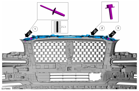
-
Drill the rivets.
Use the General Equipment: Electric Drill
-
Remove the screws.
-
Release the tabs and remove the front bumper bracket cover.
-
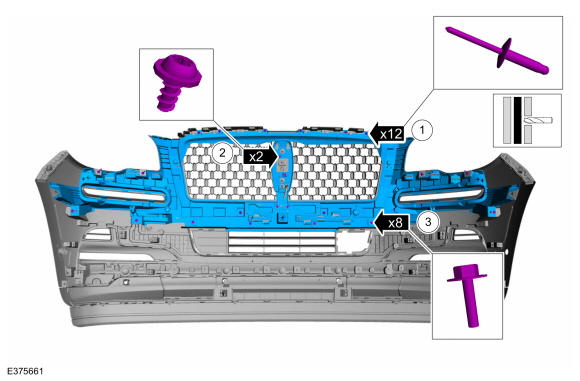
-
Drill the rivets.
Use the General Equipment: Electric Drill
-
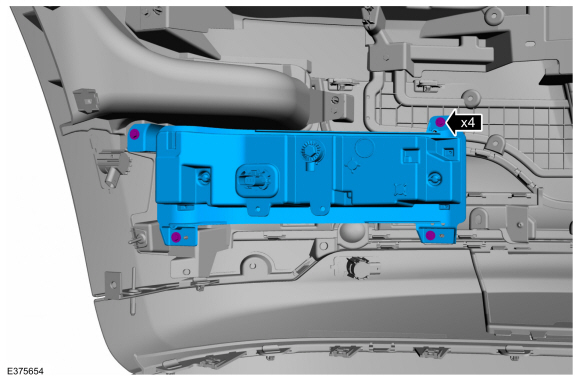
Remove the screws.
-
Remove the screws and the front bumper energy absorber.
-
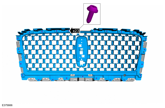
Release the tabs and remove the radiator grille assembly.
-
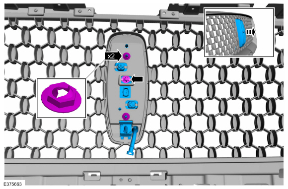
Remove the speed nuts, release the tab and remove the radiator grille emblem housing assembly.
-
If equipped.
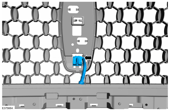
Remove the front parking aid camera and washer nozzle hose assembly.
-
If equipped.
Remove the washer nozzle hose assembly.
-
Remove the screws and the radiator grille outer panel.
-
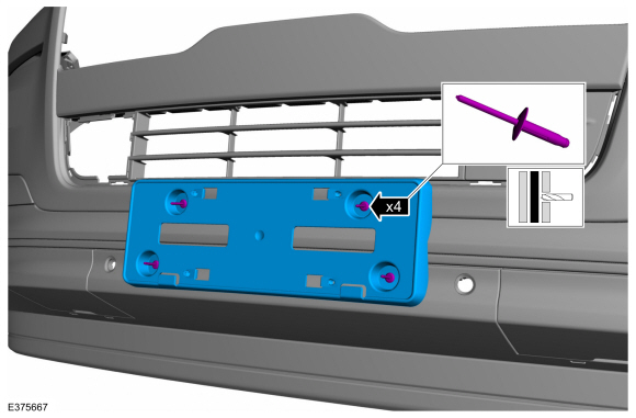
If equipped.
Drill the rivets and remove the license plate bracket.
Use the General Equipment: Electric Drill
-
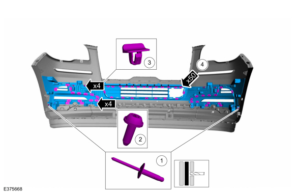
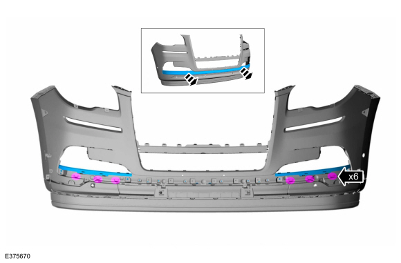
-
Drill the rivets.
Use the General Equipment: Electric Drill
-
Remove the screws.
-
Remove the push pins.
-
Release the tabs and remove the front bumper lower grille.
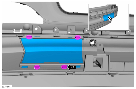
-
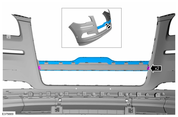
Release the tabs and remove the front bumper cover protective shield.
-
Release the tabs and remove the front bumper cover panel.
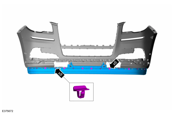
-
On both sides.
Release the tabs and remove the front tow hook cover.
-
Remove the push pins, release the tabs and remove the lower valence.
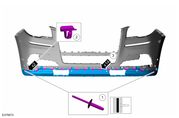
-
-
Drill the rivets.
Use the General Equipment: Electric Drill
-
Remove the push pins.
-
Release the tabs and remove the front bumper lower cover.
ASSEMBLY
-
To assemble, reverse the disassembly procedure.
Vehicles With: Parking Aid Camera
-
NOTE:
Carry out the following step if installing a new front camera.
Initialize the camera.
Refer to: Parking Aid Camera Initialization (413-13B Parking Aid - Vehicles With: Parking Aid Camera, General Procedures).
-
Carry out the 360° camera alignment.
Refer to: 360 Degree View Camera Alignment (413-13B Parking Aid - Vehicles With: Parking Aid Camera, General Procedures).
Vehicles With: Front Fog Lamps
-
Adjust the fog lamp.
Refer to: Front Fog Lamp Adjustment (417-01 Exterior Lighting, General Procedures).
Vehicles With: Front Parking Aid
-
Check the alignment of the front parking aid sensors.
Refer to: Azimuth System Check (413-13A Parking Aid, General Procedures).
Refer to: Elevation System Check (413-13A Parking Aid, General Procedures).
-
If any sensor fails the check, diagnose the sensor fault.
Refer to: Parking Aid (413-13A Parking Aid, Diagnosis and Testing).
Vehicles With: Active Park Assist
-
Check the alignment of the front active park assist sensors.
Refer to: Azimuth System Check (413-13C Parking Aid - Vehicles With: Active Park Assist, General Procedures).
-
If any sensor fails the check, diagnose the sensor fault.
Refer to: Parking Aid (413-13C Parking Aid - Vehicles With: Active Park Assist, Diagnosis and Testing).
Special Tool(s) /
General Equipment
Interior Trim Remover
Removal
NOTE:
Removal steps in this procedure may contain installation details...
Special Tool(s) /
General Equipment
Electric Drill
DISASSEMBLY
NOTE:
Disassembly steps in this procedure may contain assembly details...
Other information:
Special Tool(s) /
General Equipment
204-186
(T95T-5638-AH)
Remover, Front Differential Housing BushingTKIT-1995-FH/FLMHTKIT-1995-LMH/MH
204-187
(T95T-5638-BH)
Installer, Front Differential Housing BushingTKIT-1995-FH/FLMHTKIT-1995-LMH/MH
205-289
(T89P-1249-A)
Installer, Wheel Hub Dust SealTKIT-1988-FLMTKIT-1988-FTKIT-1989-LM
205-371
(T96T-..
Special Tool(s) /
General Equipment
Fluid Suction Gun
Universal Fluid Dispenser
Materials
Name
Specification
Motorcraft® MERCON® ULV Automatic Transmission FluidXT-12-QULV
WSS-M2C949-A, MERCON® ULV
Draining
NOTE:
It is not necessary to remove the transmission fluid filter to drain the transmission fluid.
Remove the ..
 Rear Bumper Cover. Removal and Installation
 Rear Bumper Cover. Disassembly and Assembly