Lincoln Navigator: Fuel Charging and Controls - 3.5L EcoBoost (272kW/370PS) / Port Injection Fuel Rail. Removal and Installation
Removal
-
Release the fuel system pressure.
Refer to: Fuel System Pressure Release (310-00 Fuel System - General
Information - 3.5L EcoBoost (272kW/370PS), General Procedures).
-
Disconnect the battery negative cable.
Refer to: Battery Disconnect and Connect (414-01 Battery, Mounting and Cables, General Procedures).
-
Remove the intake manifold.
Refer to: Intake Manifold (303-01 Engine - 3.5L EcoBoost (272kW/370PS), Removal and Installation).
-
Disconnect the fuel rail fuel tube quick release coupling.
Refer to: Quick Release Coupling (310-00 Fuel System - General Information - 3.5L EcoBoost (272kW/370PS), General Procedures).
-
Disconnect the fuel rail fuel tube quick release coupling.
Refer to: Quick Release Coupling (310-00 Fuel System - General Information - 3.5L EcoBoost (272kW/370PS), General Procedures).
-
Disconnect the main fuel injector harness electrical connector.
-
Remove the fuel rail bolts, then remove the fuel rail.
-
Disconnect the fuel injector electrical connectors.
-
-
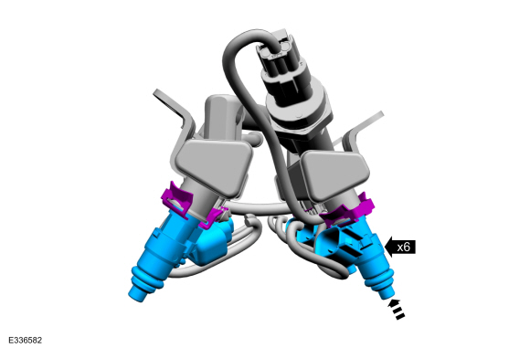
Remove the fuel injector retaining clips.
-
Remove the fuel injectors from the fuel rail.
-
Remove and discard all of the fuel injector O-ring seals.
Installation
-
NOTE:
Make sure that new fuel injector O-ring seals are installed.
-
NOTE:
The fuel injector clip can be reused if it is not damaged during removal.
If the clip is reused, the 2 sides of the clip
should be squeezed back into shape by placing it between index finger
and thumb.
-
Install the new fuel injector O-ring seals and the
fuel injector retaining clips onto the fuel injectors. Lubricate the new
fuel injector O-ring seals with clean engine oil.
Refer to: Specifications (303-01)
.
-
Install the fuel injectors into the fuel rail.
-
Connect the fuel injector electrical connectors.
-
Install the fuel rail, then install and tighten the fuel rail bolts in the following 2 stages.
Torque:
Stage 1:
Tighten to: :
89 lb.in (10 Nm)
Stage 2:
Tighten an additional: :
45°
-
Connect the main fuel injector harness electrical connector.
-
Connect the fuel rail fuel tube quick release coupling.
Refer to: Quick Release Coupling (310-00 Fuel System - General Information - 3.5L EcoBoost (272kW/370PS), General Procedures).
-
Connect the fuel rail fuel tube quick release coupling.
Refer to: Quick Release Coupling (310-00 Fuel System - General Information - 3.5L EcoBoost (272kW/370PS), General Procedures).
-
Install the intake manifold.
Refer to: Intake Manifold (303-01 Engine - 3.5L EcoBoost (272kW/370PS), Removal and Installation).
-
Connect the battery negative cable.
Refer to: Battery Disconnect and Connect (414-01 Battery, Mounting and Cables, General Procedures).
-
Pressurize the fuel system.
Refer to: Fuel System Pressure Release (310-00 Fuel System - General
Information - 3.5L EcoBoost (272kW/370PS), General Procedures).
Removal and Installation
The high-pressure fuel pump drive unit is part of the right cylinder head.
Refer to: Cylinder Head RH (303-01 Engine - 3...
Removal
NOTICE:
The turbocharger compressor vanes can be damaged by even the
smallest particles. When removing any turbocharger or engine air intake
system component, ensure that no debris enters the system...
Other information:
Special Tool(s) /
General Equipment
Self-Piercing Rivet (SPR) Remover/Installer
Belt Sander
Blind Rivet Gun
Air Body Saw
MIG/MAG Welding Equipment
Materials
Name
Specification
Seam SealerTA-2-B, 3M™ 08308, LORD Fusor® 803DTM
-
Repair
NOTICE:
Do not begin removal of the vehicle body side until the replaceme..
Special Tool(s) /
General Equipment
303-1633Remover, Roller Rocker FollowerTKIT-2014D-ROW3TKIT-2014D-FL_ROW
303-1633-01Remover, Roller Rocker Follower
Removal
NOTE:
This procedure should be used when removing and replacing
the clipped roller finger follower or hydraulic lash adjuster and the
camshafts are not removed.
LH side rocker arm
..


 High-Pressure Fuel Pump Drive Unit. Removal and Installation
 Throttle Body. Removal and Installation