Lincoln Navigator: Exterior Trim and Ornamentation / Rear Door Moulding. Removal and Installation
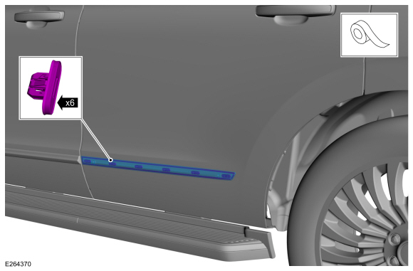
Removal
NOTE: Removal steps in this procedure may contain installation details.
NOTE: SWB (Short wheel base) shown, LWB (Long wheel base) similar.
NOTE: LH side shown, RH side similar.
-
NOTICE: To avoid damage to moulding, only use moderate force.
NOTE: Make sure that a new component is installed.
Using a non-marring trim removal tool, disengage the retainer clips, release adhesive tape and remove moulding.
 |
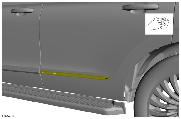
-
Clean the door panel using isopropyl alcohol or equivalent cleaner, allow to flash.
 |
Installation
-
To install, reverse the removal procedure.
 Power Running Board (PRB) Motor. Removal and Installation
Removal
NOTE:
Removal steps in this procedure may contain installation details.
NOTE:
The power running board motor and drive bracket are serviced as an assembly...
 Rear Door Upper Moulding. Removal and Installation
Removal
NOTE:
Removal steps in this procedure may contain installation details.
NOTE:
LH side shown, RH side similar.
Fore Rear Door Upper Moulding
Lower the door window glass...
Other information:
Lincoln Navigator 2018-2026 Workshop Manual: Speaker Audio Test. General Procedures
Activation NOTE: The procedure used to download the audio files varies, depending on the web browser used. Using a suitable web browser, download all of the diagnostic sound tracks to a suitable USB drive. 125Hz Sample 100Hz Sample 80Hz Sample 63Hz Sample 50Hz Sample 4..
Lincoln Navigator 2018-2026 Workshop Manual: Powertrain/Drivetrain Mount Neutralizing. General Procedures
Adjustment NOTE: Refer to the appropriate section and procedure for special instructions on loosening and tightening mount fasteners. With the vehicle in NEUTRAL, position it on a hoist. Refer to: Jacking and Lifting (100-02 Jacking and Lifting, Description and Operation). Loosen, but do not remove, the powertrain/drivetrain mount fasteners. ..
Categories
- Manuals Home
- 4th Gen Lincoln Navigator Service Manual (2018 - 2026)
- SYNC Module [APIM]. Removal and Installation
- Neutral Flat Tow Activation and Deactivation. General Procedures
- Body Control Module (BCM). Removal and Installation
- Body and Paint
- Transmission Fluid Level Check. General Procedures
Wheel to Hub Runout Minimization. General Procedures
Check
NOTE: Wheel-to-hub optimization is important. Clearance between the wheel and hub can be used to offset or neutralize the Road Force® or run-out of the wheel and tire assembly. For every 0.001 inch of wheel-to-hub clearance, the Road Force® can be affected between 1 and 3 pounds depending on the tire stiffness.
NOTE: The example below illustrates how the clearance between the wheel and the hub can be used to offset the high spot of radial run-out or Road Force®. Following the procedure will make sure of the best optimization.
Position the wheel and tire assembly on the vehicle so that the high spot location of radial run-out or Road Force® is at the 6 o'clock position and