Lincoln Navigator: Exterior Trim and Ornamentation / Rear Door Upper Moulding. Removal and Installation
Removal
NOTE:
Removal steps in this procedure may contain installation details.
NOTE:
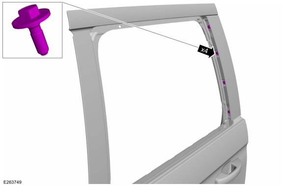
LH side shown, RH side similar.
Fore Rear Door Upper Moulding
-
Lower the door window glass.
-
Remove the upper belt moulding screw at rear of the door.
-
Remove the pin type retainers and position aside the rear door weatherstrip at front of rear door.
-
Remove the upper belt moulding screw at front of the door.
-
Using a non-marring trim tool, disengage the moulding from the channel in the door and remove the moulding.
-
Remove the rear door trim panel.
Refer to: Rear Door Trim Panel (501-05 Interior Trim and Ornamentation)
.
-
Remove the pin-type retainers and the upper interior rear door trim.
-
Position aside the rear door fore top run weatherstrip.
-
Remove the screws.
Torque:
13 lb.in (1.5 Nm)
-
Detach the front edge of the moulding from the door frame and pull the moulding outward to remove.
Aft Rear Door Upper Moulding
-
Lower the door window glass.
-
Remove the upper belt moulding screw at rear of the door.
-
Remove the pin type retainers and position aside the rear door weatherstrip at front of rear door.
-
Remove the upper belt moulding screw at front of the door.
-
Using a non-marring trim tool, disengage the moulding from the channel in the door and remove the moulding.
-
Remove the rear door glass top run.
Refer to: Rear Door Glass Top Run (501-11 Glass, Frames and Mechanisms)
.
-
Remove the screws.
Torque:
13 lb.in (1.5 Nm)
-
Remove the rear door rear moulding.
Installation
-
To install, reverse the removal procedure.
Removal
NOTE:
Removal steps in this procedure may contain installation details.
NOTE:
SWB (Short wheel base) shown, LWB (Long wheel base) similar...
Removal
NOTE:
Removal steps in this procedure may contain installation details.
NOTE:
LH side shown, RH side similar.
All vehicles
Remove the RH side rear wheel...
Other information:
Removal
NOTE:
LH side shown, RH side similar.
Remove the wheel and tire.
Refer to: Wheel and Tire (204-04A Wheels and Tires, Removal and Installation).
Remove the bolts and the push pins.
Torque:
15 lb...
Materials
Name
Specification
Motorcraft® Metal Brake Parts CleanerPM-4-A, PM-4-B, APM-4-C
-
Removal
NOTE:
Removal steps in this procedure may contain installation details.
Remove the wheel and tire...


 Rear Door Moulding. Removal and Installation
 Rear Fender Splash Shield. Removal and Installation