Lincoln Navigator: Climate Control System - General Information / Thermostatic Expansion Valve. Removal and Installation
Removal
NOTICE: During the removal or installation of components, cap, tape or otherwise appropriately protect all openings and tubes/fittings to prevent the ingress of dirt or other contamination. Remove caps, tape and other protective materials prior to installation.
NOTE: Removal steps in this procedure may contain installation details.
-
Recover the refrigerant. Refer to the appropriate Recovery procedure in Group 412.
-
Remove the battery tray.
Refer to: Battery Tray (414-01 Battery, Mounting and Cables, Removal and Installation).
-
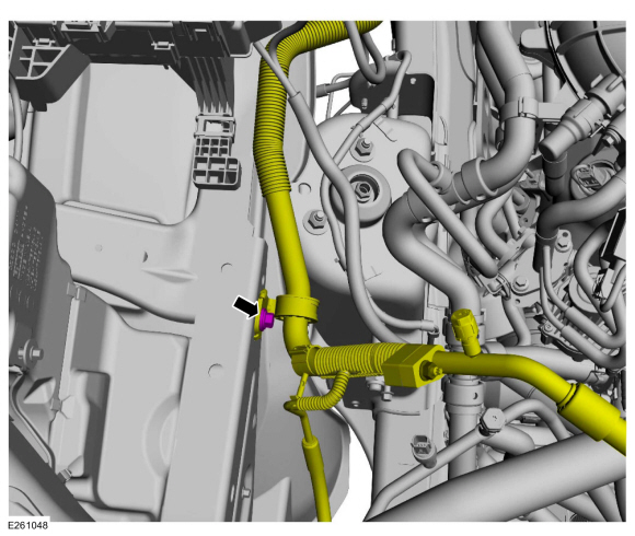
Remove the thermostatic expansion valve manifold tube assembly bracket retainer.
Torque: 133 lb.in (15 Nm)
 |
-
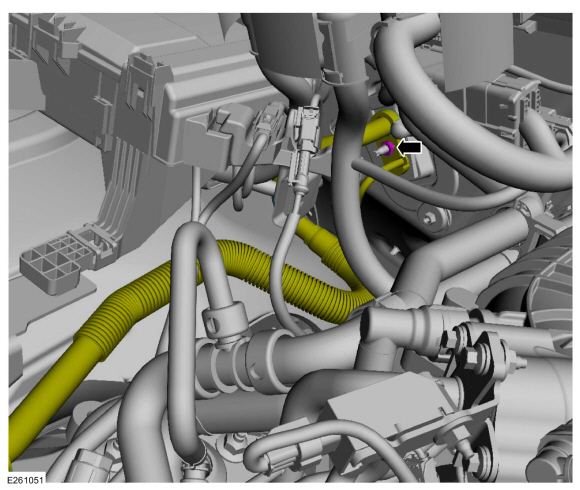
Remove the thermostatic expansion valve manifold and tube assembly nut, position the thermostatic expansion valve manifold and tube assembly aside.
-
Make sure to cover any open ports to prevent debris from entering the system.
Torque: 80 lb.in (9 Nm)
-
Make sure to cover any open ports to prevent debris from entering the system.
 |
-
Remove the thermostatic expansion valve bolts, and the thermostatic expansion valve.
-
Make sure to cover any open ports to prevent debris from entering the system.
Torque: 71 lb.in (8 Nm)
-
Make sure to cover any open ports to prevent debris from entering the system.
 |
Installation
-
To install, reverse the removal procedure.
-
NOTICE: Only use the specified material to lubricate the seals.
Install and lubricate new O-ring seals. Refer to the appropriate Specifications in Group 412.
-
Lubricate the refrigerant system with the correct amount
of clean PAG oil. Refer to the appropriate Refrigerant Oil Adding
procedure in Group 412.
 Temperature Door Actuator. Removal and Installation
Removal
NOTE:
Note the position of the components before removal.
Disconnect the electrical connector.
Remove the retainers, the temperature door actuator and the cam...
 Thermostatic Expansion Valve Manifold and Tube Assembly. Removal and Installation
Special Tool(s) /
General Equipment
Flat Headed Screw Driver
Locking Pliers
Removal
NOTICE:
During the removal of components, cap, tape or otherwise
appropriately protect all openings to prevent the ingress of dirt or
other contamination...
Other information:
Lincoln Navigator 2018-2025 Workshop Manual: Spark Plugs. Removal and Installation
Removal Remove the ignition coil-on-plugs. Refer to: Ignition Coil-On-Plug (303-07 Engine Ignition - 3.5L EcoBoost (272kW/370PS), Removal and Installation). Use compressed air to remove any foreign material in the spark plug well before removing the spark plugs...
Lincoln Navigator 2018-2025 Workshop Manual: Brake and Clutch Systems Health and Safety Precautions. Description and Operation
WARNING: Do not use any fluid other than clean brake fluid meeting manufacturer's specification. Additionally, do not use brake fluid that has been previously drained. Following these instructions will help prevent system contamination, brake component damage and the risk of serious personal injury...
Categories
- Manuals Home
- 4th Gen Lincoln Navigator Service Manual (2018 - 2025)
- Windshield Washer Pump. Removal and Installation
- Remote Function Actuator (RFA) Module. Removal and Installation
- Power Running Board (PRB). Diagnosis and Testing
- Front Seat. Removal and Installation
- Satellite Radio Antenna. Removal and Installation
Rear Camber Adjustment. General Procedures
Special Tool(s) / General Equipment
Wheel Alignment SystemActivation
NOTICE: Suspension fasteners are critical parts that affect the performance of vital components and systems. Failure of these fasteners may result in major service expense. Use the same or equivalent parts if replacement is necessary. Do not use a replacement part of lesser quality or substitute design. Tighten fasteners as specified.
Using alignment equipment and the manufacturer's instructions, measure the rear camber.Use the General Equipment: Wheel Alignment System