Lincoln Navigator: Engine Cooling - 3.5L EcoBoost (272kW/370PS) / Coolant Pump. Removal and Installation
Special Tool(s) /
General Equipment
| Hose Clamp Remover/Installer |
Materials
| Name |
Specification |
Motorcraft® Yellow Concentrated Antifreeze/Coolant
VC-13-G |
WSS-M97B57-A1
|
Motorcraft® Orange Concentrated Antifreeze/Coolant
VC-3-B |
WSS-M97B44-D
|
Removal
-
Drain the cooling system.
Refer to: Engine Cooling System Draining, Vacuum Filling and Bleeding
(303-03 Engine Cooling - 3.5L EcoBoost (272kW/370PS), General
Procedures).
-
Remove the LH
CAC Intake Pipe.
Refer to: Charge Air Cooler (CAC) Intake Pipe (303-12 Intake Air
Distribution and Filtering - 3.5L EcoBoost (272kW/370PS), Removal and
Installation).
-
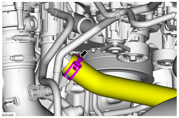
-
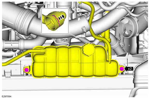
Remove the spring clip and disconnect the lower coolant hose.
-
Remove the bolts and position the degas bottle aside.
-
Loosen the coolant pump pulley bolts.
-
Remove the accessory drive belt.
Refer to: Accessory Drive Belt (303-05 Accessory Drive - 3.5L EcoBoost (272kW/370PS))
.
-
NOTICE:
Cover the A/C compressor belt to prevent coolant contamination of the belt.
Completely cover the A/C compressor belt with waterproof plastic.
-
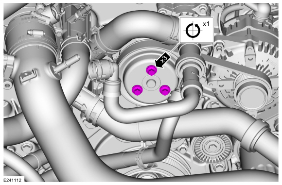
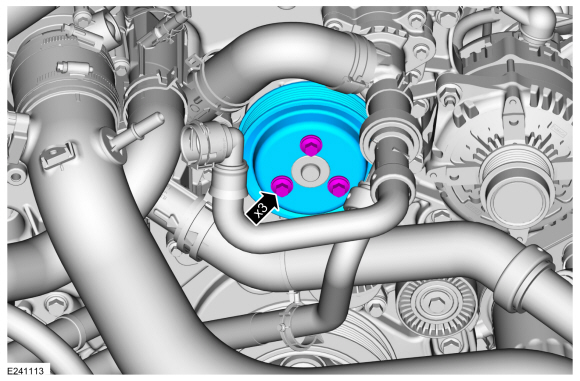
Remove the bolts and the coolant pump pulley.
-
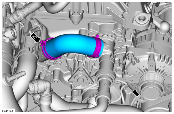
Release the clamps and remove the coolant hose.
Use the General Equipment: Hose Clamp Remover/Installer
-
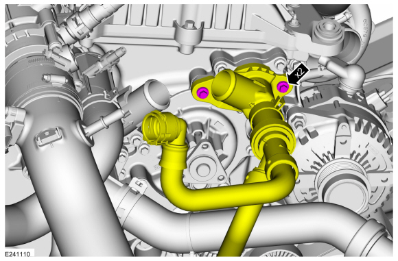
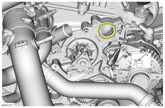
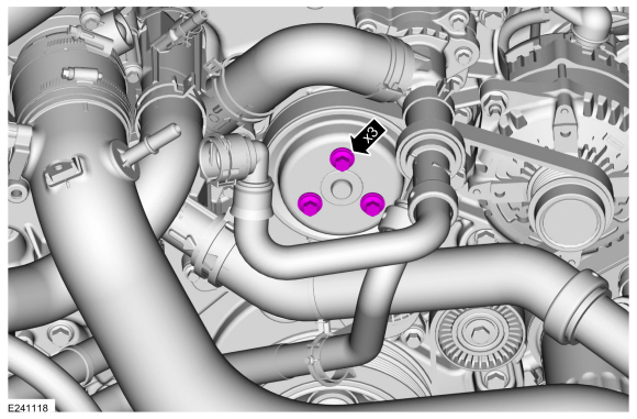
Remove the bolts and position the water pump outlet connector aside.
-
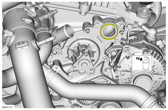
Remove and discard the O-ring seal.
-
Release the clamp and disconnect the lower radiator hose.
Use the General Equipment: Hose Clamp Remover/Installer
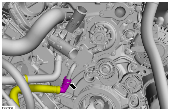
-
Disconnect the coolant hose quick release coupling.
-
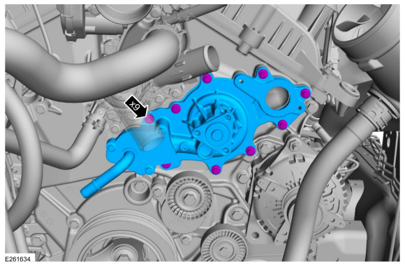
Remove the bolts and the coolant pump.
-
Remove and discard the coolant pump gasket and O-ring seal.
Installation
-
NOTICE:
Use Motorcraft® Orange Antifreeze/Coolant for
vehicles built up to 08-July-2018 and Motorcraft® Yellow
Antifreeze/Coolant for vehicles built from 09-July-2018. Failure to use
the correct coolant can degrade corrosion protection.
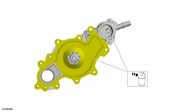
Install a new coolant pump gasket and lubricate the O-ring seal with clean engine coolant.
Material: Motorcraft® Orange Concentrated Antifreeze/Coolant
/ VC-3-B
(WSS-M97B44-D)
Material: Motorcraft® Yellow Concentrated Antifreeze/Coolant
/ VC-13-G
(WSS-M97B57-A1)
-
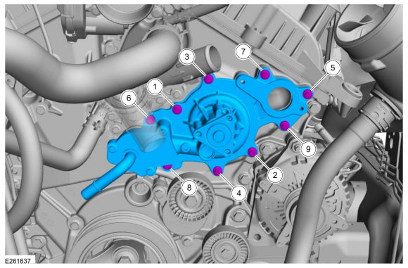
NOTE:
Components not shown for clarity.
Install the coolant pump and tighten the bolts.
Torque:
Stage 1:
89 lb.in (10 Nm)
Stage 2:
45°
-
Connect the coolant hose quick release coupling.
-
Connect the lower radiator hose and position the clamp.
Use the General Equipment: Hose Clamp Remover/Installer
-
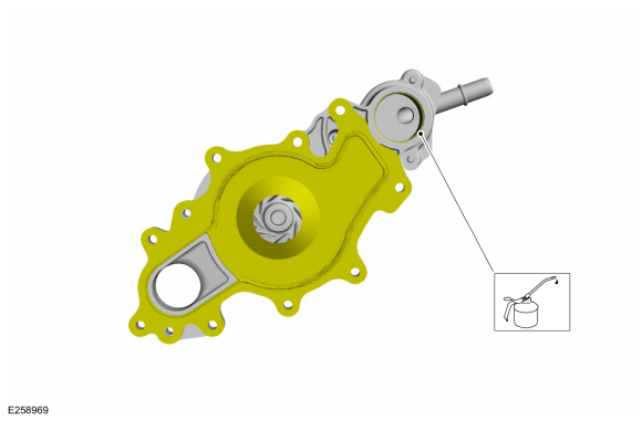
Lubricate the O-ring seal with clean engine coolant.
Material: Motorcraft® Orange Concentrated Antifreeze/Coolant
/ VC-3-B
(WSS-M97B44-D)
-
Position the water pump outlet connector and tighten the bolts.
Torque:
Stage 1:
89 lb.in (10 Nm)
Stage 2:
45°
-
Install the coolant hose.
Use the General Equipment: Hose Clamp Remover/Installer
-
Position the coolant pump pulley and install the bolts finger tight.
-
Install the accessory drive belt.
Refer to: Accessory Drive Belt (303-05 Accessory Drive - 3.5L EcoBoost (272kW/370PS))
.
-
Remove the plastic from the A/C compressor belt.
-
Tighten the coolant pump pulley bolts.
Torque:
18 lb.ft (24 Nm)
-
-
Position the degas bottle and install the bolts.
Torque:
62 lb.in (7 Nm)
-
Connect the lower degas bottle hose and install the spring clip.
-
Install the LH
CAC Intake Pipe.
Refer to: Charge Air Cooler (CAC) Intake Pipe (303-12 Intake Air
Distribution and Filtering - 3.5L EcoBoost (272kW/370PS), Removal and
Installation).
-
Fill and bleed the cooling system.
Refer to: Cooling System Draining, Vacuum Filling and
Bleeding (303-03 Engine Cooling - 3.5L EcoBoost (272kW/370PS))
.
Removal
NOTE:
Removal steps in this procedure may contain installation details.
Drain the cooling system.
Refer to: Engine Cooling System Draining, Vacuum Filling and Bleeding
(303-03 Engine Cooling - 3...
Removal
With the vehicle in NEUTRAL, position it on a hoist.
Refer to: Jacking and Lifting (100-02 Jacking and Lifting, Description and Operation)...
Other information:
Removal
NOTE:
Removal steps in this procedure may contain installation details.
NOTE:
LH (left-hand) side DDM (driver door module) shown.
RH (right-hand) side PDM (passenger door module) similar.
NOTE:
If installing a new module, it is necessary to
upload the module configuration information to the diagnostic scan tool
prior to removing the module...
Removal
Open the media bin.
Release the tabs and position the media hub out.
Disconnect the electrical connectors and remove the media hub...

 Block Heater. Removal and Installation
 Cooling Fan Motor and Shroud. Removal and Installation
 205-1016
 205-153
(T80T-4000-W)
205-153
(T80T-4000-W)
 205-D061
(D83T-4205-C2)
205-D061
(D83T-4205-C2)